Radar apparatus, radar apparatus controlling method

Inactive Publication Date: 2006-01-19
FUJITSU LTD +1
View PDF15 Cites 95 Cited by
  • Summary
  • Abstract
  • Description
  • Claims
  • Application Information

AI Technical Summary

Benefits of technology

[0019] According to the present invention, a long- and short-range radar which conventionally requires two long- and short-range radars can be implemented with only one radar. Accordingly, comparing with a configuration using three apparatuses, where long- and short-range radars, which are manag

Problems solved by technology

A conventional FM-CW (Frequency Modulation-Continuous Wave) radar system can detect a target in a distance range of several meters to a hundred and several tens of meters, but has a difficulty in the detection of a target in an extremely short range such as approximately 10 centimeters with the same degree of accuracy.
In the meantime, an ultra-short pulse radar system can detect a target in a distance range of approximately 10 centimeters to a ten and several meters with high accuracy, but has a difficulty in the detection of a target in a distance range of 100 meters or more.
Such a system has a disadvantage that its configuration becomes complex, and its cost becomes expensive in comparison with a case where a detection system is imple

Method used


Image

  • Radar apparatus, radar apparatus controlling method
  • Radar apparatus, radar apparatus controlling method
  • Radar apparatus, radar apparatus controlling method

Examples


Embodiment Construction

[0034] Preferred embodiments according to the present invention are described in detail below with reference to the drawings.

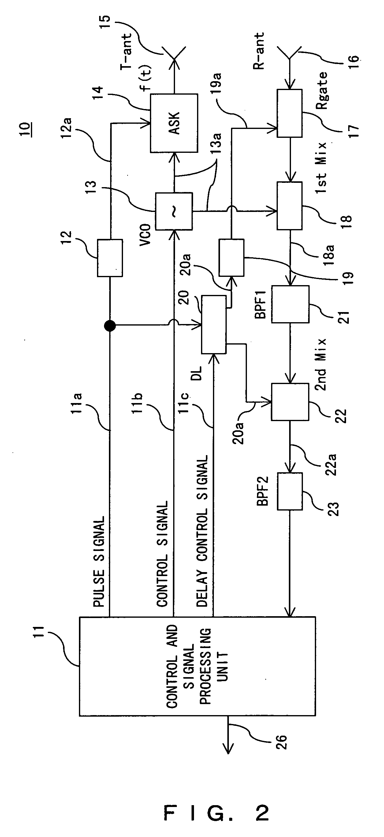
[0035]FIG. 2 is a block diagram exemplifying a configuration of a radar apparatus according to a preferred embodiment of the present invention. FIGS. 3 to 6 are schematics exemplifying an action of the radar apparatus.

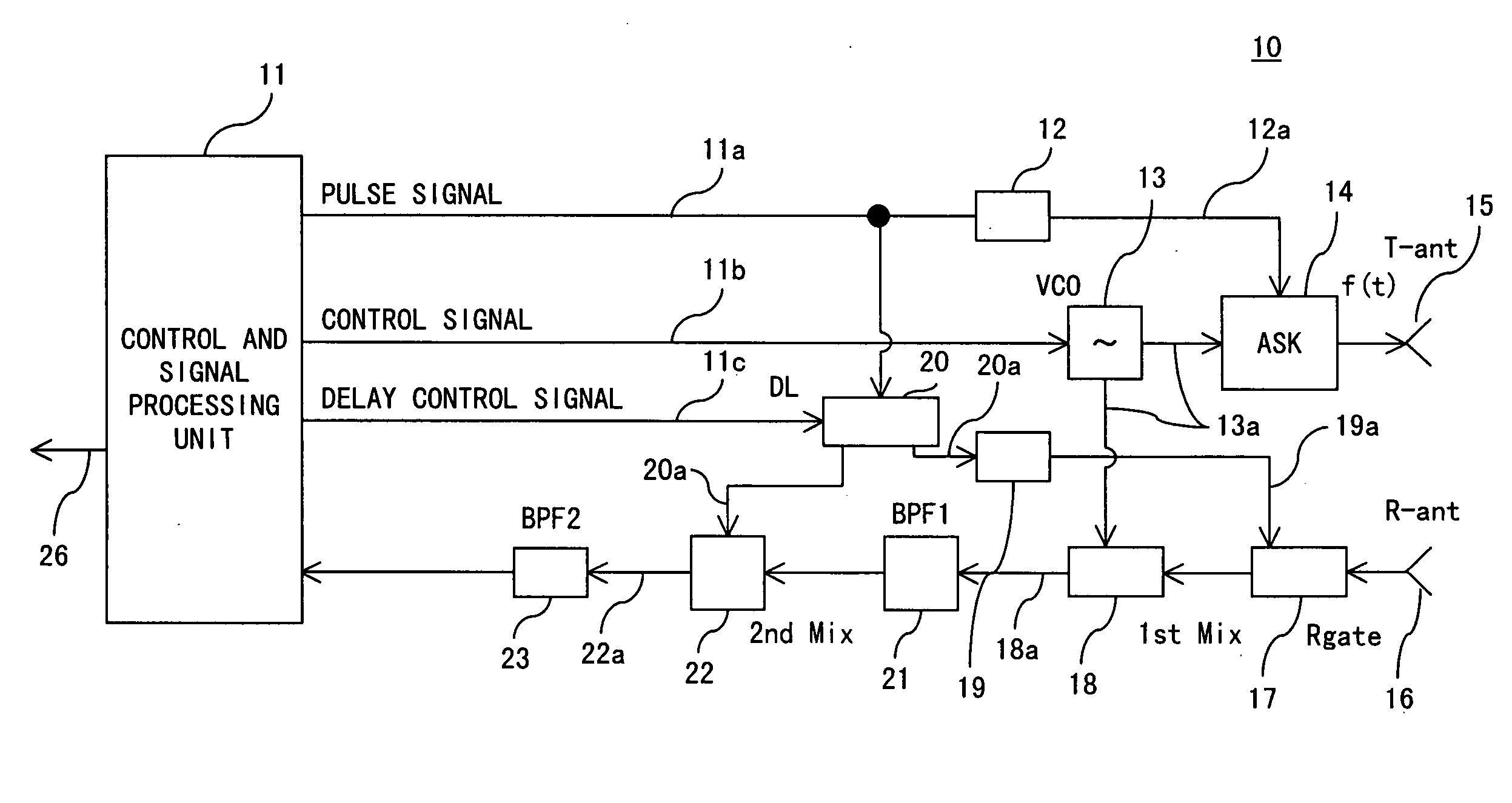
[0036] The radar apparatus according to this preferred embodiment comprises: a transmitting unit having a transmitter high-frequency FM modulation oscillator 13, a transmitter high-frequency ASK switching circuit 14, a short pulse generation circuit 12, and a transmitter antenna 15; a receiving unit having a receiving antenna 16, a receiver high-frequency gate circuit 17, a first mixer 18 (first frequency converter), a short pulse generation circuit 19, a programmable delay circuit 20, a band-pass filter 21 (first band-pass filter), a second mixer 22 (second frequency converter), and a band-pass filter 23 of a beat frequency band (second band-p...


PUM


Abstract

A radar apparatus comprises: a transmitter unit having a high-frequency oscillating unit whose oscillation frequency is variable, and a pulse amplitude modulating unit for amplitude-modulating a pulse of a transmission high-frequency signal output from the high-frequency oscillating unit with a first control pulse signal; a receiver unit having a gating unit for controlling ON/OFF of an input of a received high-frequency signal with a second control pulse signal; and a controlling and signal processing unit for controlling the transmitter unit and the receiver unit, and for switching a first operation mode for making the apparatus function as an FM-CW radar, and a second operation mode for making the apparatus function as a pulse radar.

Description

BACKGROUND OF THE INVENTION [0001] 1. Field of the Invention [0002] The present invention relates to a radar technique, and more particularly, to an effective technique being applied to detect a target positioned in a wide range from a long to short range. [0003] 2. Description of the Related Art [0004] Attention is paid to a millimeter wave radar technique intended to observe, for example, an obstruction on a road, and a traffic condition in operation management the car with the radar. [0005] A conventional FM-CW (Frequency Modulation-Continuous Wave) radar system can detect a target in a distance range of several meters to a hundred and several tens of meters, but has a difficulty in the detection of a target in an extremely short range such as approximately 10 centimeters with the same degree of accuracy. In the meantime, an ultra-short pulse radar system can detect a target in a distance range of approximately 10 centimeters to a ten and several meters with high accuracy, but ha...

Claims


Application Information

Patent Timeline
IPC IPC(8): G01S13/93G01S13/08G01S13/931
CPCG01S7/02G01S13/08G01S13/582G01S2013/9321G01S13/931G01S2013/9375G01S2013/9378G01S13/87G01S2013/93272G01S2013/93271G01S13/34
Inventor DOOI, YOSHIKAZUISHII, SATOSHIYATSUKA, HIROYUKISHIMA, NOBUKAZUHITOTSUYA, MASAKI
Owner FUJITSU LTD
Why Eureka
Try Eureka