Supercharge Your Innovation With Domain-Expert AI Agents!

Liquid-crystal display driving device

a technology of liquid crystal display and driving device, which is applied in the direction of static indicating device, non-linear optics, instruments, etc., can solve the problems of image blurring effect image blurring effect,

Inactive Publication Date: 2006-01-19
KK TOSHIBA
View PDF4 Cites 11 Cited by
  • Summary
  • Abstract
  • Description
  • Claims
  • Application Information

AI Technical Summary

Benefits of technology

The present invention provides a method for driving an active matrix type liquid crystal display device by applying different voltages to the first and second electrodes to improve display quality. This method involves dividing a frame into two fields and applying a first voltage of one polarity to the first electrode during the first field. A second voltage is then generated by changing the polarity and magnitude of the first voltage based on a direction of the first polarity. This second voltage is applied to the first electrode during the second field. This method results in a larger polarization of the liquid crystal layer when a voltage of the first polarity is applied compared to a different voltage of the second polarity, resulting in improved display quality.

Problems solved by technology

For this reason, image-blurring effects become a problem at the time of displaying moving image.
As a result, the image blurring effects occur.
This is the cause of the image blurring effects.
In the case of the AC driving, if a DC component remains across the liquid crystal layer for a time much longer than one frame period, image sticking will occur.
Thus, although a proposal has been made for an impulse type of display using an asymmetric response liquid crystal in order to prevent image blurring effects in moving image display, the conventional driving method presents a problem of the occurrence of image sticking due to application of a DC component across the liquid crystal layer.

Method used


Image

  • Liquid-crystal display driving device
  • Liquid-crystal display driving device
  • Liquid-crystal display driving device

Examples


Embodiment Construction

[0027] First, the basic principles of an embodiment of the present invention will be described.

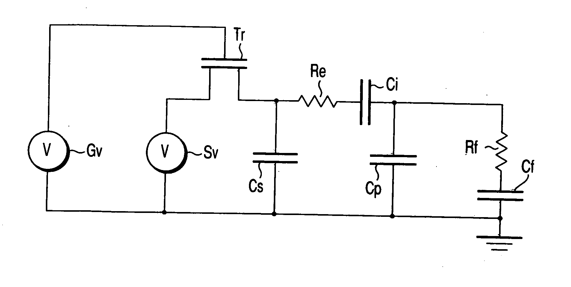
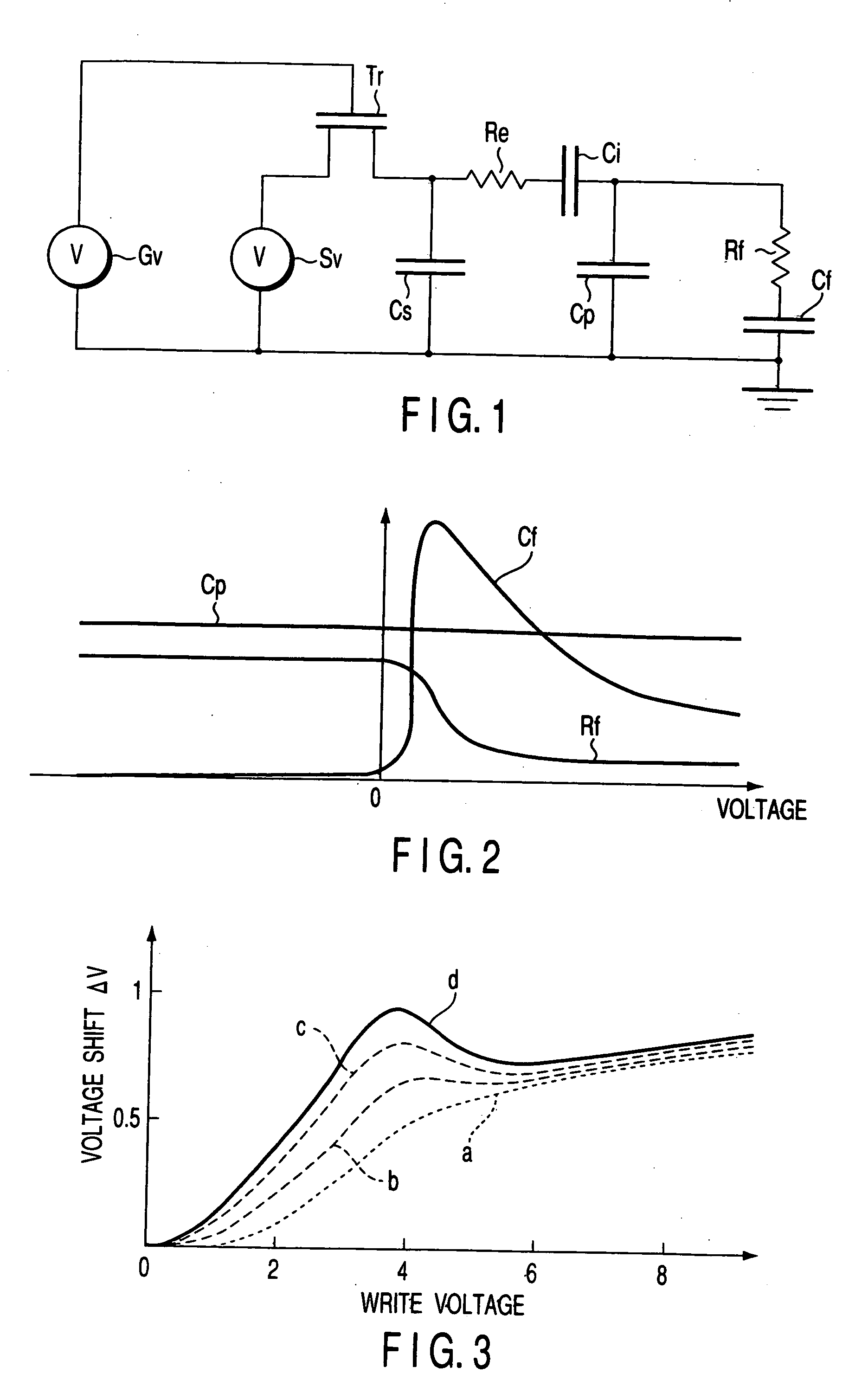
[0028]FIG. 1 shows an equivalent circuit model of the liquid crystal display device according to the embodiment of the present invention.

[0029] In FIG. 1, Cf represents the capacitance corresponding to spontaneous polarization of the liquid crystal layer (asymmetric response liquid crystal), Rf the resistance for representing the speed of response (corresponding to Cf×Rf) of the liquid crystal layer, Cp the normal dielectric capacitance of the liquid crystal layer (capacitance at high frequencies), Ci the capacitance of insulating films (including an alignment film) interposed between the liquid crystal layer and electrodes, Re the electrode-associated resistance, and Cs the storage capacitance. Further, Tr represents a thin-film transistor (TFT) used as a switching element, Gv a control signal source for on-off control of the thin-film transistor Tr, and Sv a display signal source that ...


PUM

PropertyMeasurementUnit
thicknessaaaaaaaaaa
DC voltageaaaaaaaaaa

Abstract

Disclosed is a method for driving an active matrix type liquid crystal display device including a first electrode, a second electrode, and a liquid crystal layer interposed between the first and the second electrodes, and the liquid crystal layer having a larger polarization when a voltage of a first polarity is applied to the first electrode against the second electrode than that when a voltage of a second polarity different from the first polarity is applied to the first electrode against the second electrode, the method comprising dividing a frame into a first field and a second field, applying a first voltage of the first polarity to the first electrode during the first field, generating a second voltage from the first voltage by changing its polarity, a magnitude of the second voltage being modified by an amount of ΔV (ΔV≠0) based on a magnitude of the first voltage in a direction of the first polarity when the first voltage is not zero, and applying the second voltage to the first electrode during the second field.

Description

CROSS-REFERENCE TO THE RELATED APPLICATIONS [0001] This application is based upon and claims the benefit of priority from the prior Japanese Patent Application No. 2001-188686, filed Jun. 21, 2001, the entire contents of which are incorporated herein by reference. BACKGROUND OF THE INVENTION [0002] 1. Field of the Invention [0003] The present invention relates to a method of driving a liquid-crystal display device. [0004] 2. Description of the Related Art [0005] A liquid-crystal display is generally a hold type of display that continues to hold display of the previous frame and not an impulse type of display as with CRTs (Cathode Ray Tubes). For this reason, image-blurring effects become a problem at the time of displaying moving image. [0006] In observing a moving object on a display screen, the moving object image in a frame continues to be displayed in the same position until switching is made to the next frame. Nevertheless, human eyes will continuously follow the moving object....

Claims


Application Information

Patent Timeline
Patent Type & Authority Applications(United States)
IPC IPC(8): G09G3/36G02F1/133G09G3/20
CPCG09G3/3614G09G3/3648G09G2300/0842G09G2320/0261G09G2320/02G09G2320/0204G09G2320/0257G09G2310/06G02F1/133
Inventor SAISHU, TATSUOOKUMURA, HARUHIKOTAKATOH, KOHKIYAMAGUCHI, HAJIMEHASEGAWA, REIKOBAYASHI, HITOSHIFUKUSHIMA, RIEKO
Owner KK TOSHIBA
Features
  • R&D
  • Intellectual Property
  • Life Sciences
  • Materials
  • Tech Scout
  • Unparalleled Data Quality
  • Higher Quality Content
  • 60% Fewer Hallucinations
Learn More