Molded-in light emitting diode light source

a light-emitting diode and light-emitting technology, which is applied in the direction of light-emitting devices, semiconductor devices of light-emitting devices, lighting and heating apparatus, etc., can solve the problems of increasing installation cost, short life of bulbs, and affecting the quality of light-emitting devices, so as to reduce the number of parts and thereby the necessary assembly operation, and improve the heat dissipation

Inactive Publication Date: 2006-01-19
OSRAM SYLVANIA INC
View PDF12 Cites 13 Cited by
  • Summary
  • Abstract
  • Description
  • Claims
  • Application Information

AI Technical Summary

Benefits of technology

[0008] Excellent heat dissipation is provided by the direct attachment of the light emitting diode to a thermally conductive post that is an integral part of the heat-sinking base

Problems solved by technology

While working well and being inexpensive, these bulbs have a relatively short life and, of course, the thin filament employed was always subject to breakage due to vibration.
However, these LE

Method used


Image

  • Molded-in light emitting diode light source
  • Molded-in light emitting diode light source
  • Molded-in light emitting diode light source

Examples


Embodiment Construction

[0011] For a better understanding of the present invention, together with other and further objects, advantages and capabilities thereof, reference is made to the following disclosure and appended claims taken in conjunction with the above-described drawings.

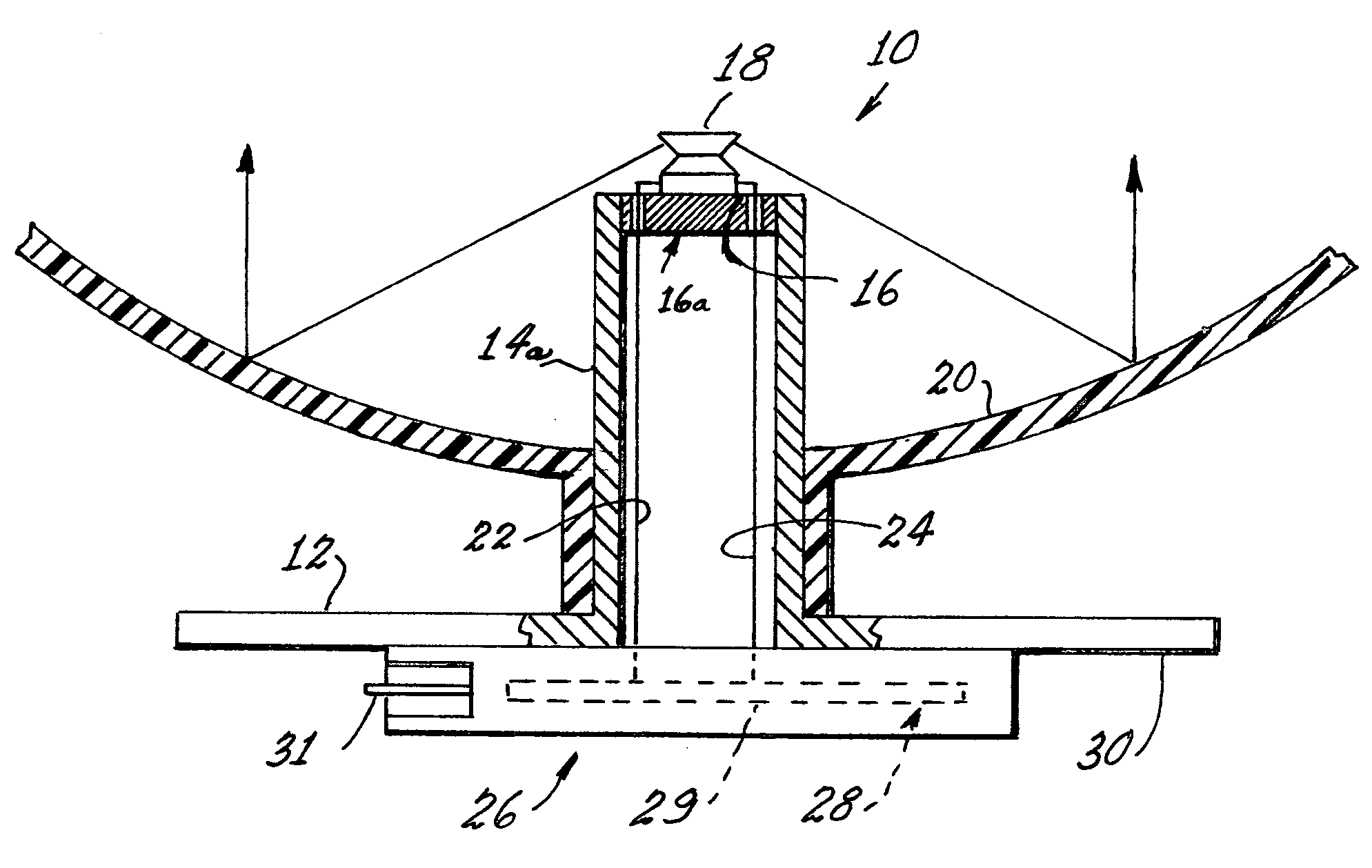
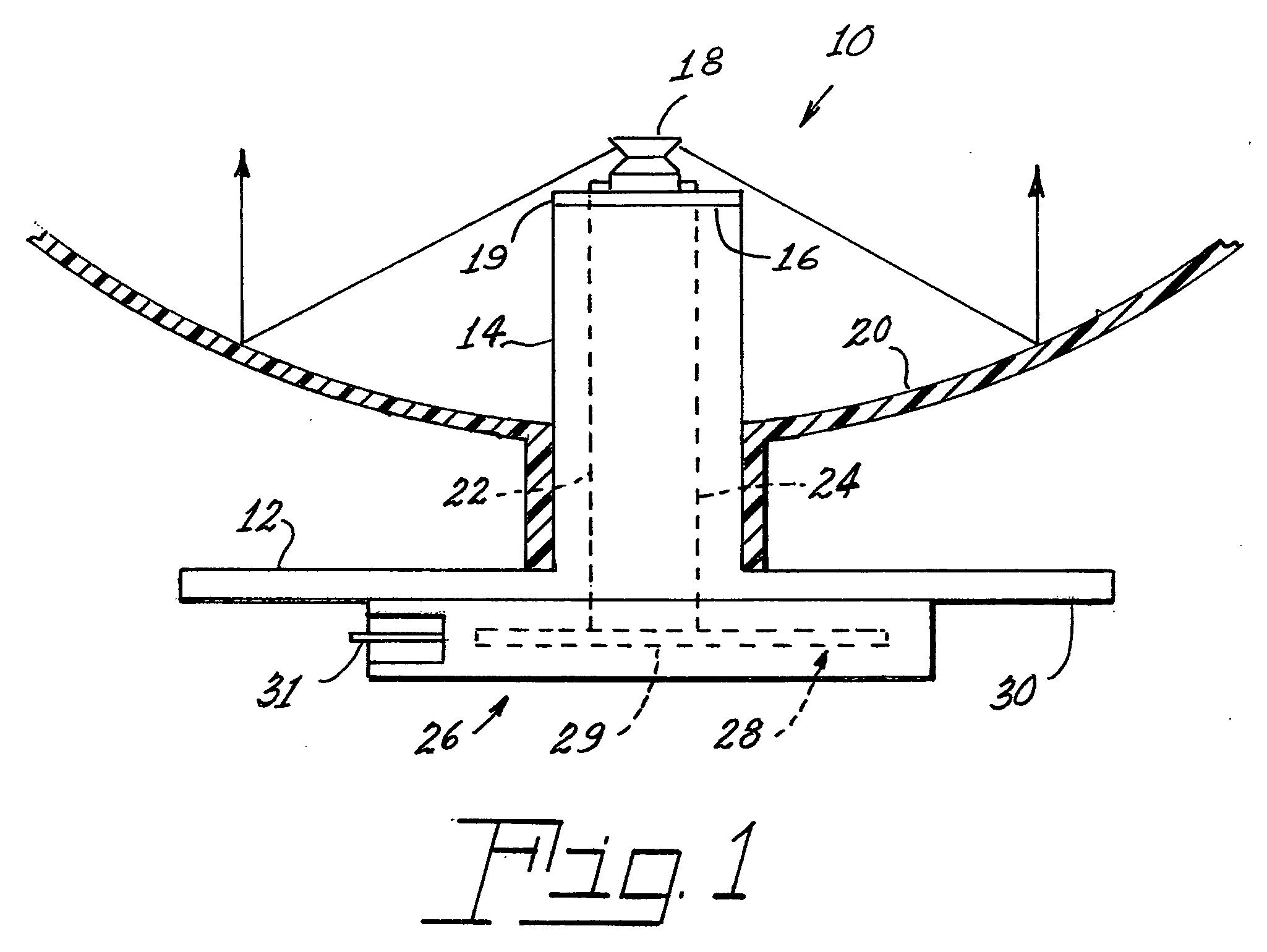
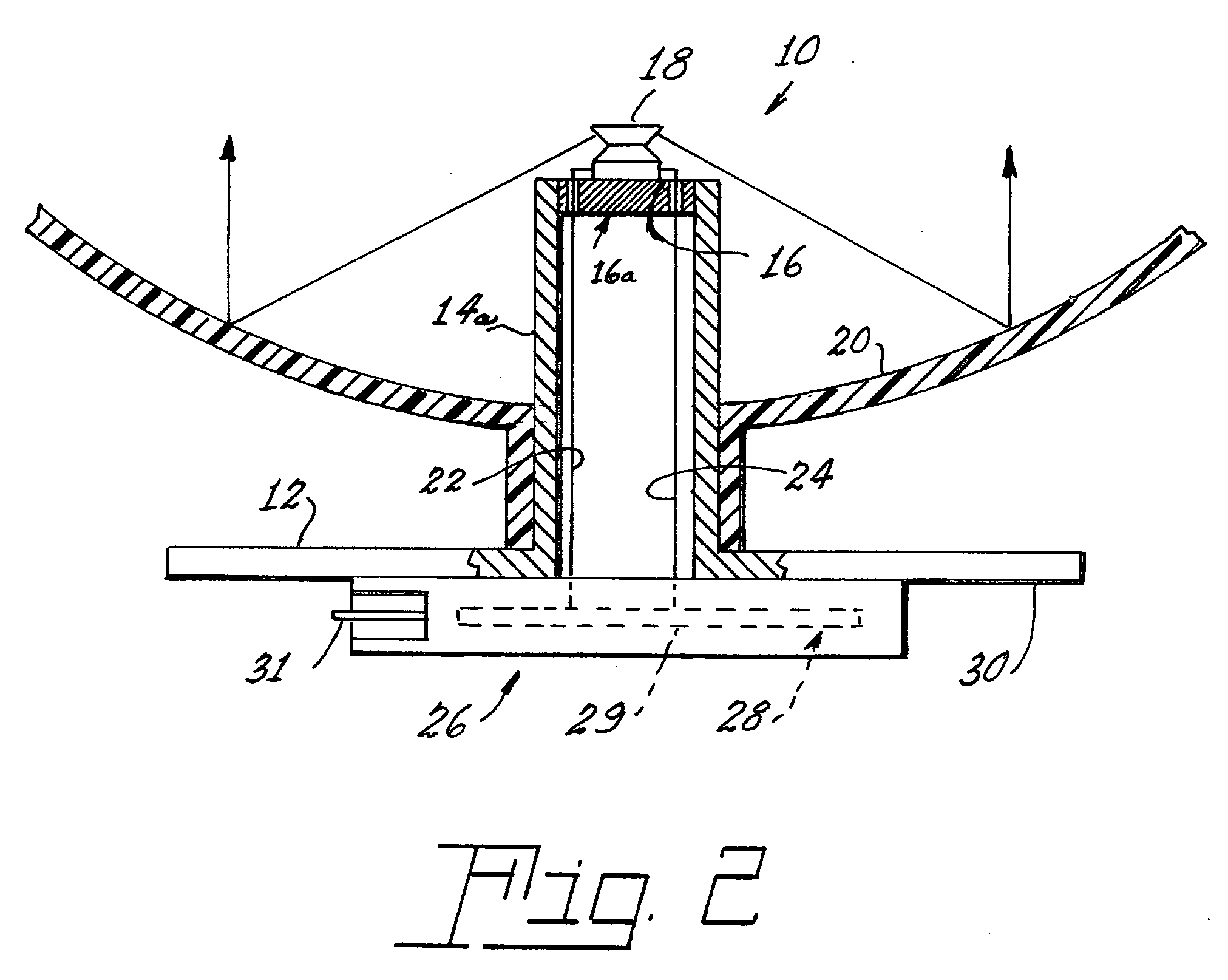
[0012] Referring now to the drawing with greater particularity, there is shown in the figure lamp assembly 10 that comprises a base 12 having an axially extending post 14 with a first surface 16 on the distal end of the post 14. The base and integral post are thermally conductive and are preferably constructed of copper or aluminum.

[0013] A thermally conductive but electrically insulating member 19 can be affixed to the first surface 16 of the post 14 and a single light emitting diode 18 can be operatively affixed to the insulating member 19, for example by a thermally conductive cement. For optimal effect the light emitting diode is side-emitting one that is axially centered on the post 14. A reflector 20 is in optical commun...


PUM


Abstract

A lamp assembly (10) has a base (12) with an axially extending post 14 having a first surface 16. The base and the post are thermally conductive. A light emitting diode (18) is operatively affixed to the first surface (16). A reflector (20) is in optical communication with the light emitting diode (18) and the reflector (20) is mechanically fixed to the base 12. Electrical connections (22, 24) extend through the base (12) to the light emitting diode (18).

Description

CROSS-REFERENCE TO RELATED APPLICATIONS [0001] This application claims priority from Provisional Patent Application No. 60 / 588,869, filed Jul. 16, 2004.TECHNICAL FIELD [0002] This invention relates to electric lamps and particularly to electric lamps utilizing a single light emitting diode (hereafter LED or LEDs) light source. More particularly the invention is concerned with an electric lamp with an LED light source coupled to a heat sink with rapid mounting features. BACKGROUND ART [0003] In the past, most automotive light sources have involved the use of incandescent bulbs. While working well and being inexpensive, these bulbs have a relatively short life and, of course, the thin filament employed was always subject to breakage due to vibration. [0004] Recently some of the automotive uses, particularly the stoplight, have been replaced by LEDs. These solid-state light sources have incredible life times, in the area of 100,000 hours, and are not as subject to vibration failures. H...

Claims


Application Information

Patent Timeline
IPC IPC(8): F21V29/00F21K99/00H01L33/48H01L33/60
CPCF21S48/215F21K9/00F21K9/68F21S43/14
Inventor COUSHAINE, CHARLES M.TUCKER, MICHAELTESSNOW, THOMAS
Owner OSRAM SYLVANIA INC
Why Eureka
Try Eureka