Loopback capability for Bi-directional multi-protocol label switching traffic engineered trunks

a trunk and multi-protocol technology, applied in the field of network operation, administration and maintenance (oa&m) functions, can solve the problems of insufficient checking of continuity and qos attributes of te trunks, lack of oa&m functions for mpls, and inability to implement approaches

Inactive Publication Date: 2006-01-19
BOODAGHIANS SAMSON
View PDF11 Cites 20 Cited by
  • Summary
  • Abstract
  • Description
  • Claims
  • Application Information

AI Technical Summary

Benefits of technology

[0017] It is an aspect of the present invention to provide a loopback OA&M function that can be introduced as an additional function to the MPLS traffic engineering framework or as part of a more comprehensive OA&M framework in MPLS. An MPLS-layer loopback function, hereinafter referred to as a loopback function, is a OA&M function providing the capability for testing parameters of traffic trunks in a MPLS network. For example, an originating LSR, i.e., an LSR constructing a loopback packet for transmission on a specific BTT, can send a loopback packet downstream to a loopback LSR. A loopback packet is a OA&M packet intended to be transmitted, from a LSR constructing the loopback packet, downstream, i.e. from the constructing LSR towards a loopback LSR. A loopback LSR is an LSR that receives the loopback packet and performs a loopback procedure for transmitting the loopback packet upstream, i.e., towards the LSR that constructed the loopback packet. The LSR that constructed the loopback packet, receives the loopback packet from the loopback LSR, and evaluates one or more BTT parameters using information provided by the loopback packet. The loopback packet may be an in-band network management packet (INMP). An INMP is a label-switched network management packet that carries OA&M information and commands. Each LSR along the BTT, receiving the loopback packet, may process the loopback packet for testing parameters of the BTT. For example, an LSR receiving a loopback packet for testing delay can perform delay measurements for the packet. Also, once the loopback packet is received by the originating LSR after the loopback procedure is performed, the originating LSR can ascertain tested BTT parameters using the received loopback packet.

Problems solved by technology

MPLS currently lacks OA&M functions that can provide the ability for ascertaining parameters of a BTT.
This approach, however, can only be implemented if the layer 3 protocol is IP.
Furthermore, this approach may be adequate for some OA&M functions (e.g, checking continuity with Ping and Traceroute) from a host to another host or server but will not be adequate for checking continuity and QoS attributes of a TE trunk.

Method used


Image

  • Loopback capability for Bi-directional multi-protocol label switching traffic engineered trunks
  • Loopback capability for Bi-directional multi-protocol label switching traffic engineered trunks
  • Loopback capability for Bi-directional multi-protocol label switching traffic engineered trunks

Examples


Embodiment Construction

1. Label Switching Router Performing Loopback

[0033]FIG. 3 illustrates MPLS network 40 and NHLFEs for LSR 1 and LER B. An originating LSR, such as ingress LER A, can activate a loopback function in an intermediate LSR or a LER. As shown using loopback arrows 12 and 13, FIG. 3 illustrates that either an intermediate LSR, such as LSR 1, or a LER, such as LER B, may be a loopback LSR. Using either LSR 1 or LER B as a loopback LSR, a loopback packet, transmitted on BTT 10 from LER A, is transmitted back to LER A on BTT 10 from the loopback LSR.

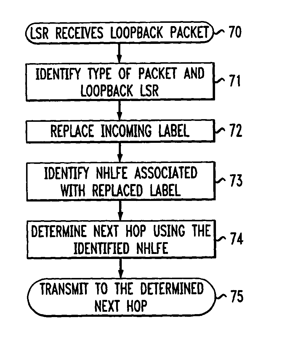
[0034]FIG. 4 is a schematic block diagram of a preferred embodiment of an LSR performing a loopback procedure in MPLS network 40. The LSR shown in FIG. 4 includes ports 50-53, processing circuitry 65 and switching fabric 60. Each of ports 50-53 includes transmitting circuitry, receiving circuitry and packet assembly circuitry, as is known in the art. Ports 50-53 are connected to processing circuitry 65 through switching fabric 60. The switching ...


PUM


Abstract

A system and method for introducing a loopback capability for Multi-Protocol Label Switching (MPLS) bi-directional traffic trunks are discussed. MPLS is an emerging technology, which integrates Internet Protocol (IP) routing with label switching techniques. MPLS intends to provide new capabilities in the area of traffic engineering for IP networks. These traffic engineering capabilities will have to be combined with a set of complementary operation, administration and maintenance (OA&M) functions for effectively managing and operating MPLS-based networks. One such function is loopback. A loopback function provides the capability to transmit a OA&M packet on one or more segments of a bi-directional traffic trunk (BTT) in a MPLS network. Using a loopback function, parameters of a BTT, such as connectivity, delay and other Quality of Service (QoS) parameters, can be tested. The system and method provide different techniques for implementing loopback in an MPLS network.

Description

[0001] This is a continuation of U.S. patent application Ser. No. 09 / 589,464, filed Jun. 7, 2000, which is hereby incorporated by reference.FIELD OF THE INVENTION [0002] The present invention relates generally to network operation, administration, and maintenance (OA&M) functions for communication networks. More particularly, the present invention relates to a loopback function for networks employing label switching techniques. BACKGROUND OF THE INVENTION [0003] A typical digital communications network has a network architecture that is based upon the Open Systems Interconnection (OSI) Reference Model for providing communication between a multiplicity of interconnected digital end systems or “nodes.” The OSI Reference Model divides networking protocols into seven layers, which, in ascending order of abstraction, are: 1) the physical layer, 2) the data-link layer, 3) the network layer, 4) the transport layer, 5) the session layer, 6) the presentation layer, and 7) the application lay...

Claims


Application Information

Patent Timeline
Patent Type & Authority Applications(United States)
IPC IPC(8): H04J3/14H04L12/26H04L12/56
CPCH04L12/2697H04L43/08H04L45/50H04L43/50H04L43/0811
Inventor BOODAGHIANS, SAMSON
Owner BOODAGHIANS SAMSON
Why Eureka
Try Eureka