
Propel/repel dispenser

Inactive Publication Date: 2006-01-19
FEDERAL PACKAGE NETWORK
View PDF4 Cites 12 Cited by
  • Summary
  • Abstract
  • Description
  • Claims
  • Application Information

AI Technical Summary

Benefits of technology

[0012] A further feature of the invention is to provide a “click” feature in the dispenser which provides a sound and feel to a consumer upon propelling or repelling product within the dispenser. The “click” feature is provided by a screw trigger which involves at least one, preferably two, main extensions or flaps projecting outward from the screw structure in the lower part of the screw structure above the turn screw, and at least one, preferably a plurality of, mating rib(s) extending inward from a wall surface of the dispenser body, preferably the base wall of the dispenser body. The mating ribs are structured to provide a predetermined amount of pressure and response and are placed in alternate contact between the extension(s) or flap(s) of the “click” feature. Upon rotation of the turn screw to propel or repel the elevator on the screw to dispense or retract product, a consumer will hear, as well as feel, a “click” upon the interaction of the extension(s) or flap(s) with the mating rib(s). Such provides a control for the amount of product dispensed or retracted. Preferably two extensions are used with a plurality of ribs, e.g., 7, so as to provide smaller increments upon which a click is heard and felt. This provides for a greater control of the amount of the product propelled or repelled.
[0013] Another feature of the invention is a screw retention means. Conventional screw retention means are either solid conical structures or multi-segmented structures within the bottom wall of the dispenser body. The retention means of the invention comprises a single slot positioned opposite a gate location in the bottom or base wall of the dispenser body through which the screw structure extends. The single slot provides for flexibility during assembly of the screw in the dispenser body while also maintaining strength to retain the screw in the dispenser body. Situating the single slot opposite the gate optimizes the structure based on the flow of plastic during molding of the dispenser body.

Problems solved by technology

In the general operation of a typical screw operated push-up applicator, a user turns the control knob causing the threaded shaft of the screw to turn, and thereby cause the elevator to travel inside the barrel with concomitant movement of the product up or down from the dispensing end of the barrel.
Deficiencies in existing stick applicators make them less than optimal in use.
First, the amount of product dispensed is difficult to control because it is indiscriminately dispensed when the control knob is turned.
If too much of the product is extended, the stick can break.
If too little is extended, inadequate application of the product results or repeated application is required.
Second, accidental dispensing can be a problem with existing stick applicators.
While other stick applicator structures are known which provide for incremental dispensing, such structures are complex requiring multiple components of interrelating structures.
This is expensive in terms of materials, time, and labor in assembly during the manufacturing process for dispensing lipstick from the holder.

Method used


Image

  • Propel/repel dispenser
  • Propel/repel dispenser
  • Propel/repel dispenser

Examples


first embodiment

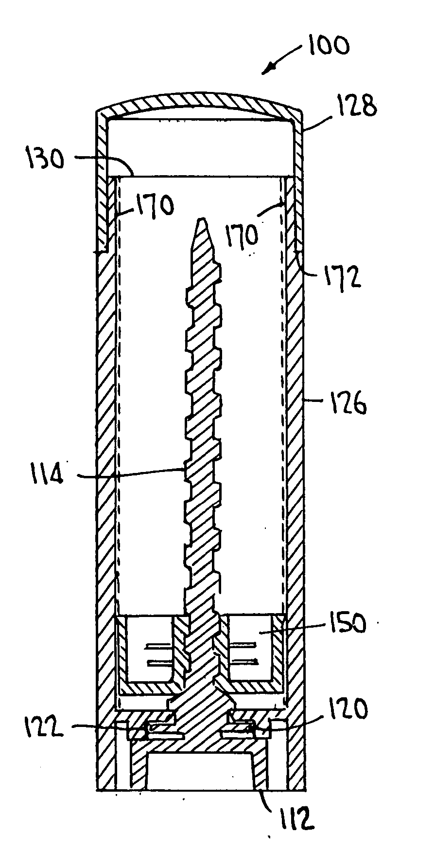
[0094] In the elevator 150, the internal screw thread 154 has a leading edge 153 which is a flat straight edge, as shown for example in FIGS. 30 and 31.

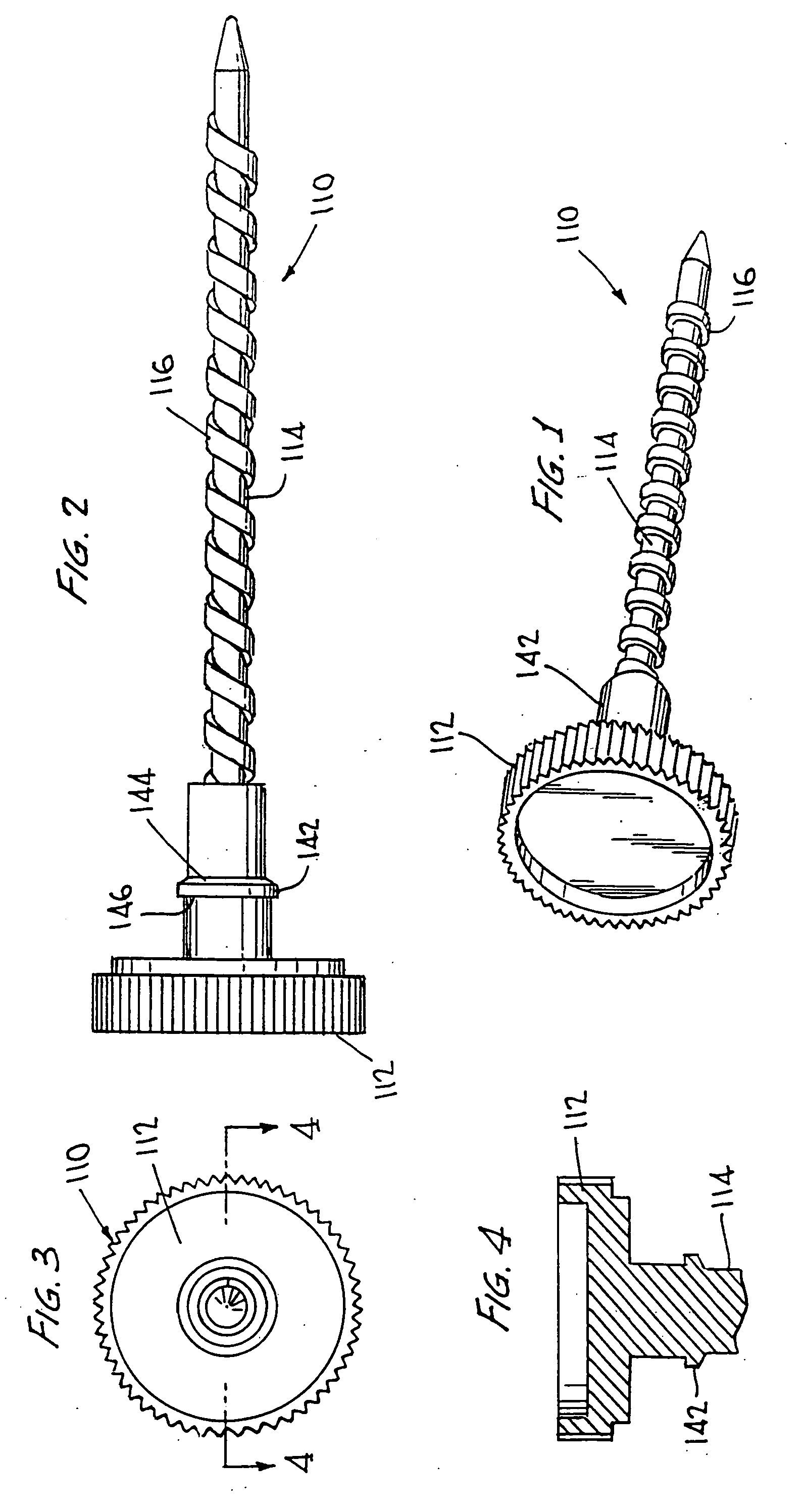
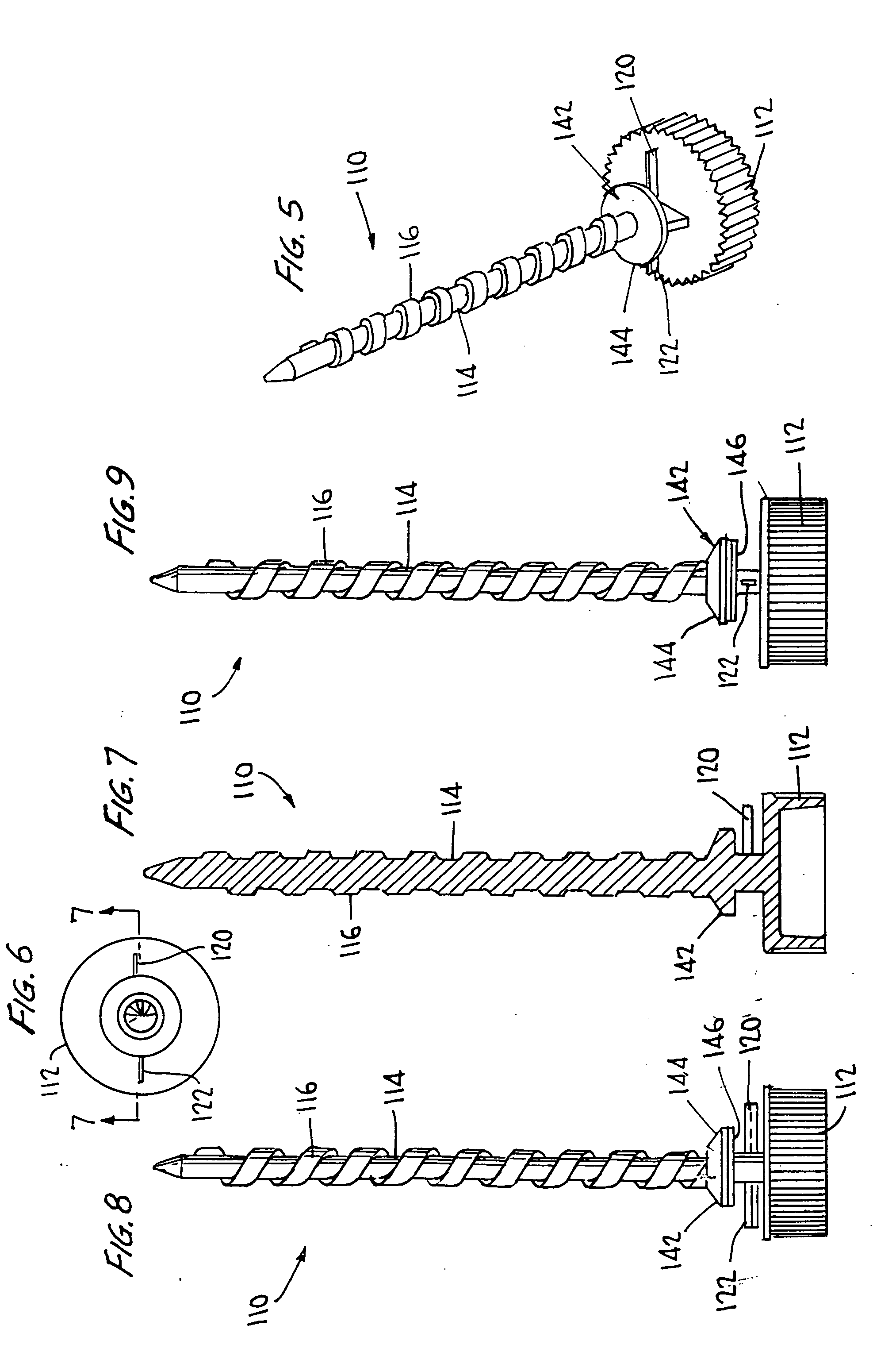
[0095] Any suitable screw structure 110 having a suitable lead screw thread 116 on the upright member 114 may be used with the elevator 150 shown in FIGS. 29-37. However, a preferred screw structure 110 has a lead screw thread 116 with a leading edge 117 that is a flat straight edge, as shown for example in FIG. 38. The flat straight leading edge 117 of the lead screw thread 116 corresponds to the flat straight leading edge 153 of the internal screw thread 154 to provide engagement of the threads.

[0096]FIG. 39 shows a top perspective view of a second embodiment of the elevator 150. FIG. 40 shows a bottom perspective view of the second embodiment of the elevator 150 of FIG. 39. FIG. 41 shows a side exterior view of the second embodiment of the elevator 150 of FIG. 39 including dotted lines showing interior structure thereof. FIG. 42 ...

second embodiment

[0097] In the elevator 150, the internal screw thread 154 has a leading edge 153′ which is an angled edge, as shown for example in FIGS. 39, 40 and 42.

[0098] Any suitable screw structure 110 having a suitable lead screw thread 116 on the upright member 114 may be used with the elevator 150 shown in FIGS. 39-42. However, a preferred screw structure 110 has a lead screw thread 116 with a leading edge 117′ that is an angled edge, as shown for example in FIG. 43. The angled leading edge 117′ of the lead screw thread 116 corresponds to the angled edge 153′ of the internal screw thread 154 to provide engagement of the threads. Also, the angled leading edges 117′, 153′ improve the initial engagement of both threads.

[0099] The embodiments of the elevator 150 as shown in FIGS. 39-42 also preferably comprise at least one widthwise internal projection 156 to provide for structure for holding the product in place within the elevator 150 once the dispenser body 126 is filled with product.

[0100...


PUM


Abstract

A propel / repel dispenser having one or more features in combination to provide improved manufacture, assembly and use of the dispenser is described. Such features include a wide single lead thread, a “click” feature to provide sound and feel to a user so that propelling and repelling can be controlled, and a retention means involving a single slot extending from a central opening through which a screw structure passes upon assembly of the dispenser.

Description

RELATED APPLICATIONS [0001] This application hereby claims the benefit under 35 U.S.C. § 119(e) of U.S. Provisional Application Ser. No. 60 / 588,767, filed Jul. 19, 2004, entitled PROPEL / REPEL DISPENSERS.FIELD OF INVENTION [0002] The invention is directed to propel / repel dispensers, in particular containing one or a combination of features providing for improved manufacture, assembly and consumer use. Inventive features disclosed include a single lead thread for the internal screw structure, a “click” feature which provides sound and feel to a consumer to indicate advance of the product in the dispenser upon propelling or repelling, and a single slot retention means for holding the screw structure in place in a dispenser body upon assembly. BACKGROUND OF THE INVENTION [0003] Stick applicators having various dispensing structures are generally known as being useful for dispensing various products including lip balms, lipsticks, deodorants, and the like. Stick applicators may take the ...

Claims


Application Information

Patent Timeline
IPC IPC(8): B43K21/08B43K23/00
CPCA45D40/04
Inventor SKAKOON, JAMESFULLER, KEVIN S.BENSON, GREG J.
Owner FEDERAL PACKAGE NETWORK
Features
  • Generate Ideas
  • Intellectual Property
  • Life Sciences
  • Materials
  • Tech Scout
  • Unparalleled Data Quality
  • Higher Quality Content
  • 60% Fewer Hallucinations
Learn More