Welding method

Inactive Publication Date: 2006-01-19
AIRBUS UK
View PDF24 Cites 30 Cited by
  • Summary
  • Abstract
  • Description
  • Claims
  • Application Information

AI Technical Summary

Benefits of technology

[0003] It is an object of the present invention to produce a method of welding two work-pieces together that eliminates

Problems solved by technology

It has been observed that the formation of at least some cracks in the methods of the prior art tends to occur in the work-piece near the interface between the alloy and the weld, in regions where there has been partial liquefaction of the alloy due to the heat generated when welding.
It is thought that such cr

Method used


Image

  • Welding method
  • Welding method
  • Welding method

Examples


Embodiment Construction

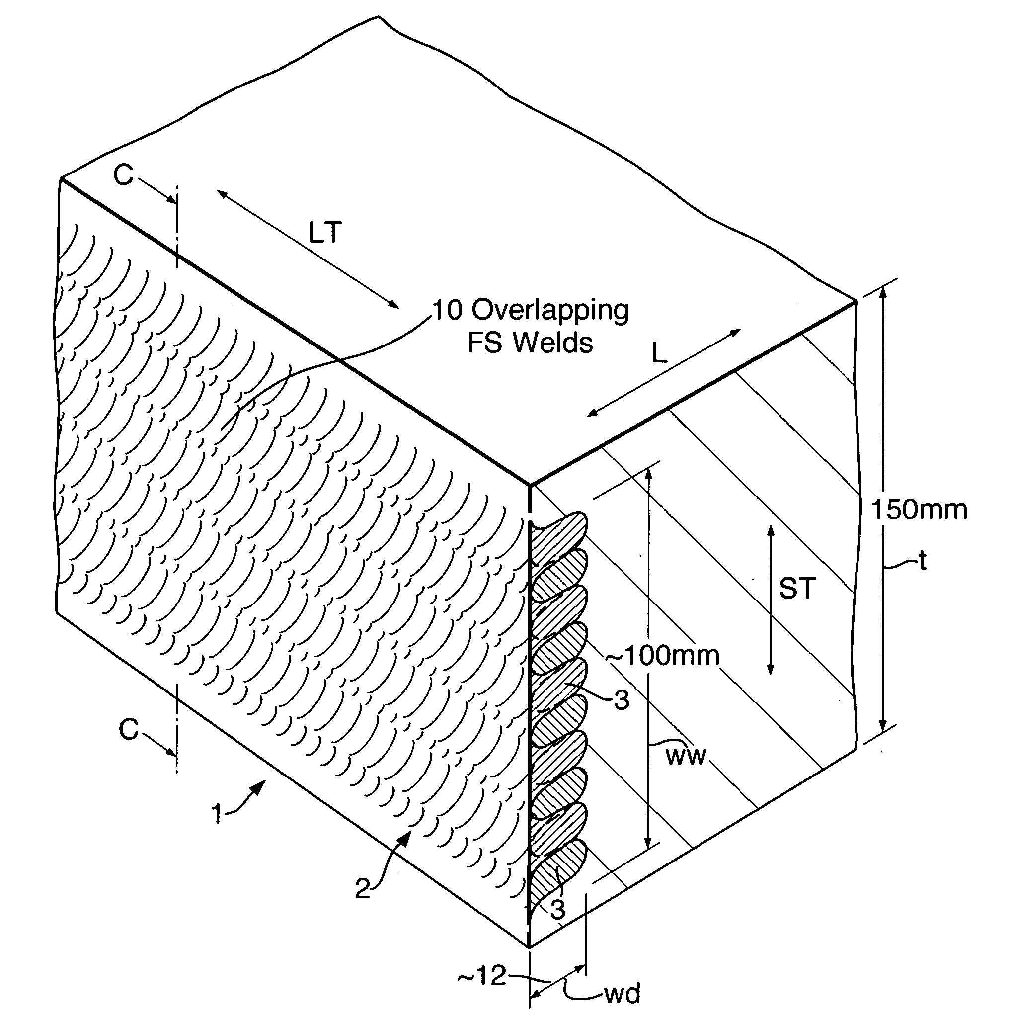
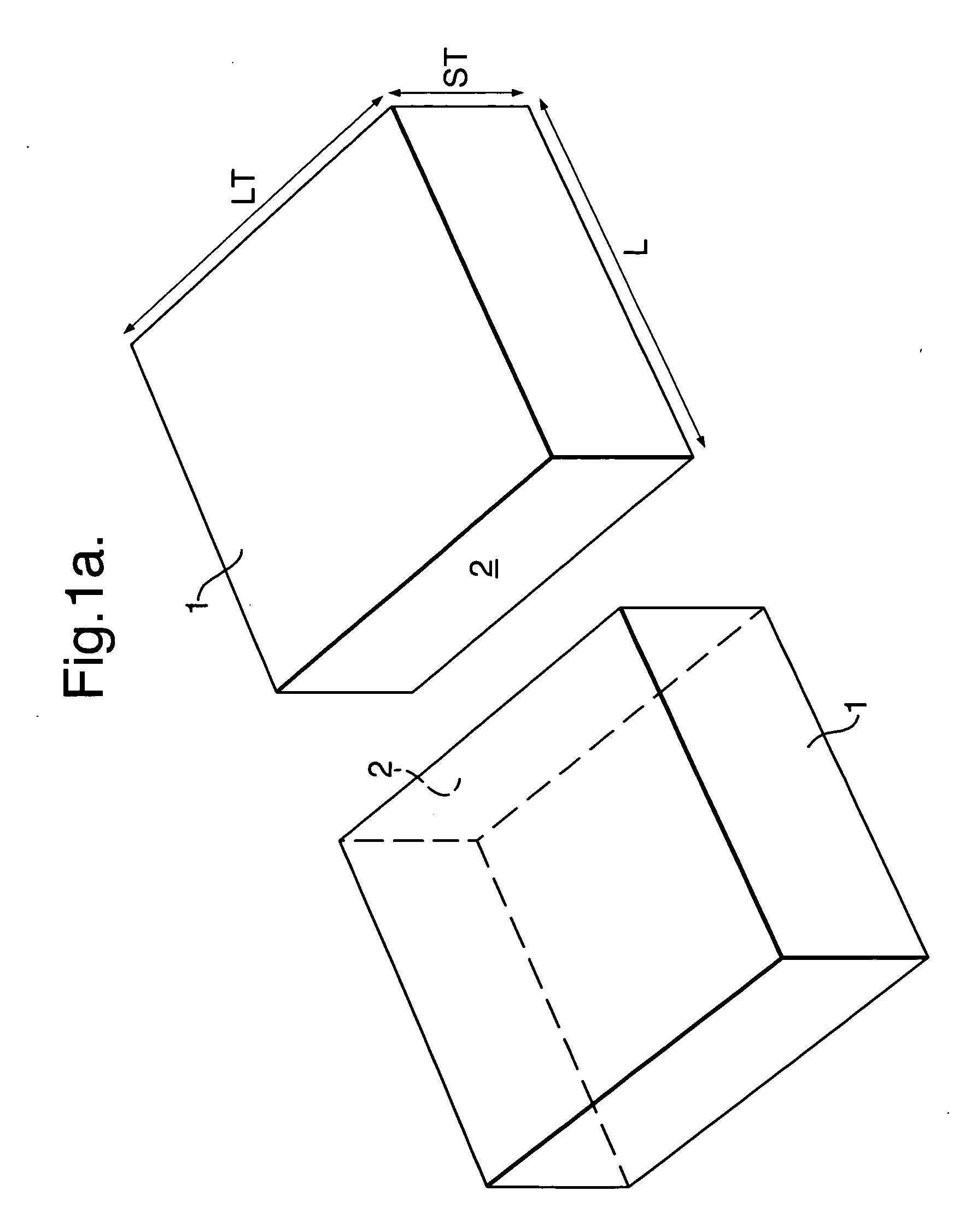
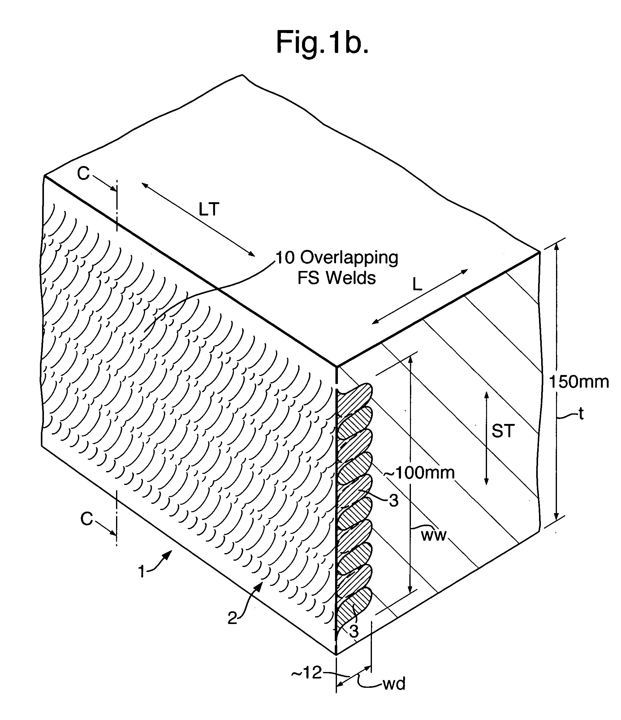
[0052] The first embodiment of the invention relates to an experiment in which two rolled plates were welded together. The rolled plates 1 before being joined are illustrated schematically in FIG. 1a. The plates were made by rolling in the longitudinal direction of the plates (represented by arrow L in the drawings). The direction of the width of the plate is represented by arrow LT (i.e. the Long Transverse direction). The direction of the thickness of the plate is represented by arrow ST (i.e. the Short Transverse direction). The rolled plates 1 have a thickness t (in direction ST) of 150 mm. The plate was made from a 7000 series aluminium alloy in T7651 temper condition. The alloy used comprises Aluminium, Zinc, Copper and Magnesium. The alloy had a relative high content of zinc (>6 wt. %). This alloy was chosen because of the known difficulties associated with fusion welding the alloy.

[0053] The microstructure of the respective sides 2 of the plates 1 to be joined was modified ...


PUM

PropertyMeasurementUnit
Fractionaaaaaaaaaa
Depthaaaaaaaaaa
Depthaaaaaaaaaa

Abstract

Two aluminium alloy work-pieces are welded together. Firstly, a portion (2) of each work-piece (1) is prepared, the preparation including the performance of a surface treatment, such as friction stir welding, that results in a region (A) extending from the exterior surface into the work-piece having a grain structure that is finer than the grain structure of the work-piece outside (region C) that region. Then the work-pieces are welded together by means of a fusion welding process, such as electron beam welding, that joins the respective prepared portions (2) of the two work-pieces (1). The preparation of the work-pieces is so performed that said region (A) extends into the work-piece to a depth that exceeds the depth of material (region D) that is caused to melt during the fusion welding process.

Description

BACKGROUND OF THE INVENTION [0001] The present invention relates to welding two metal work-pieces together and relates in particular, but not exclusively, to welding together two relatively thick work-pieces made from metal alloys that have been prepared for use in the manufacture of aircraft components. [0002] When manufacturing aircraft components it is sometimes necessary or desirable to weld together thick work-pieces for example solid blocks of aluminium alloy having a thickness of 50 mm or greater. The alloy will typically be an aluminium alloy that has been treated so that it has certain mechanical properties necessary for the alloy to be suitable for use in the manufacture of aircraft components. As a result, the microstructure of the alloy is formed of relatively coarse elongate grains that are generally oriented parallel to each other. Welding blocks of aluminium of such a thickness is generally performed by means of a fusion welding process such as an electron beam (EB) w...

Claims


Application Information

Patent Timeline
IPC IPC(8): B23K15/00B23K9/235B23K20/12B23K20/24
CPCB23K9/235B23K15/0033Y10T403/477B23K20/1275B23K20/24B23K20/122
Inventor ILYUSHENKO, ROSTYSLAVMAZIARZ, ROBERT JANDAVIES, HUW
Owner AIRBUS UK
Why Eureka
Try Eureka