Boat windshield with vent structure

a technology for venting and boats, which is applied in the field of venting for boats, can solve the problems that the desire of boaters remains unaddressed in the prior art, and achieve the effect of reducing condensation

Inactive Publication Date: 2009-08-27
N A TAYLOR CO INC
View PDF2 Cites 13 Cited by
  • Summary
  • Abstract
  • Description
  • Claims
  • Application Information

AI Technical Summary

Benefits of technology

[0007]It is, therefore, one aspect of the invention to provide a mechanism to reduce the formation of condensation on the interior of a boat windshield.
[0008]It is yet another aspect of the invention to provide a simple mechanism removes condensation from the interior surface of a boat windshield, once formed.
[0009]One embodiment of the invention provides for a vent positioned at the bottom of a boat windshield, permitting air to be directed from a position exterior to the windshield, through the vent, to an air deflector. The deflector directs the air across the interior of the windshield to reduce or eliminate the formation of condensation on the interior surface of the windshield.
[0010]Another embodiment of the invention provides for the positioning of a vent at a top of a boat windshield, permitting air to be directed from a position exterior to the windshield, through the vent, to an air deflector. The deflector directs the air across the interior of the windshield to reduce or eliminate the formation of condensation on the interior surface of the windshield.
[0014]With respect to the closure system, the invention provides for a first plate, a plurality of first openings defined through the first plate, a second plate disposed slidably behind the first plate, and a plurality of second openings defined through the second plate. The first and the second plates are slidably disposed adjacent to one another such that, in an open position, the first and second openings are in register with one another thereby permitting air flow through the air passageway and, in a closed position, the first and second openings are not in register with one another thereby preventing air flow through the air passageway.

Problems solved by technology

This desire by boaters remains unaddressed by the prior art.

Method used


Image

  • Boat windshield with vent structure
  • Boat windshield with vent structure
  • Boat windshield with vent structure

Examples


Embodiment Construction

(s) OF THE INVENTION

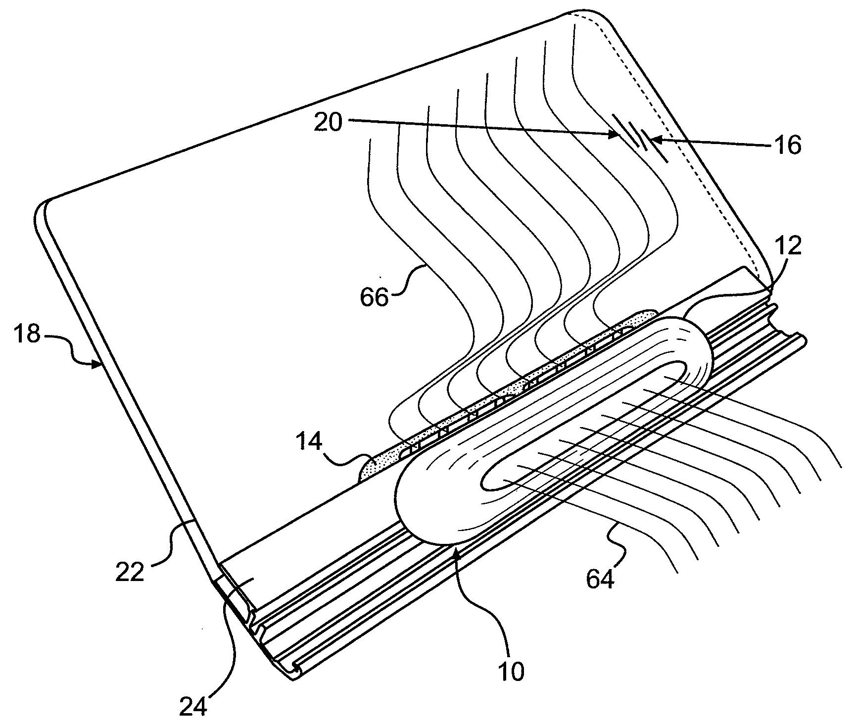
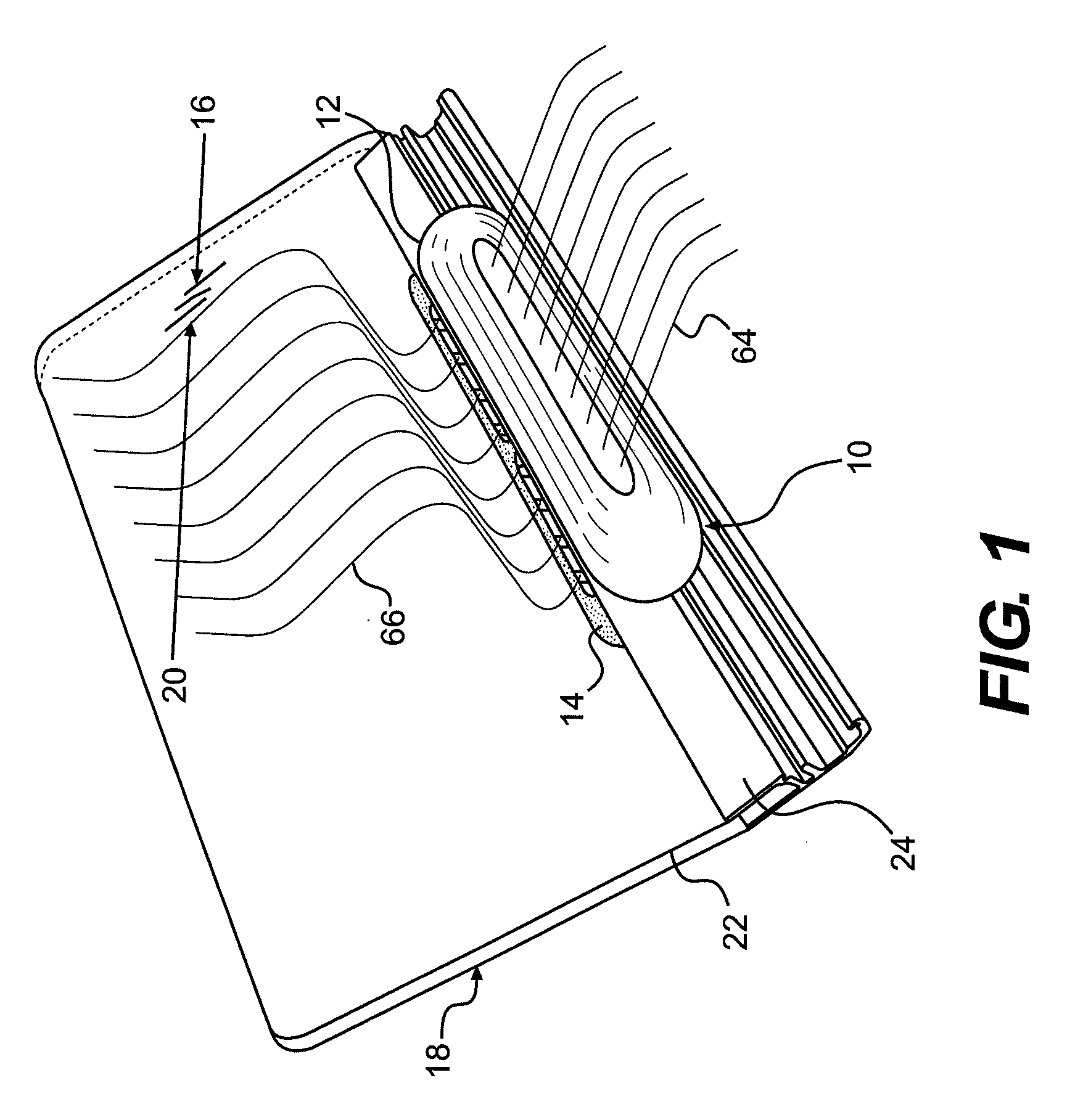
[0025]FIG. 1 provides a perspective illustration of the vent 10 of the invention. The vent 10 includes an air intake 12 and an air discharge 14. The air intake 12 is positioned at a front side 16 of a windshield 18. The air discharge 14 is positioned at a rear side 20 of the windshield 18. The windshield 18, at least in the illustrated embodiment, includes a transparent pane 22 and a bottom rail 24. The transparent pane 22 may be made of any transparent material suitable for the windshield 18. Typically, the transparent pane 22 is made from glass. As should be appreciated by those skilled in the art, however, the transparent pane 22 may be made from a substitute material, such as polycarbonate, clear acrylic, or the like, without departing from the scope of the invention.

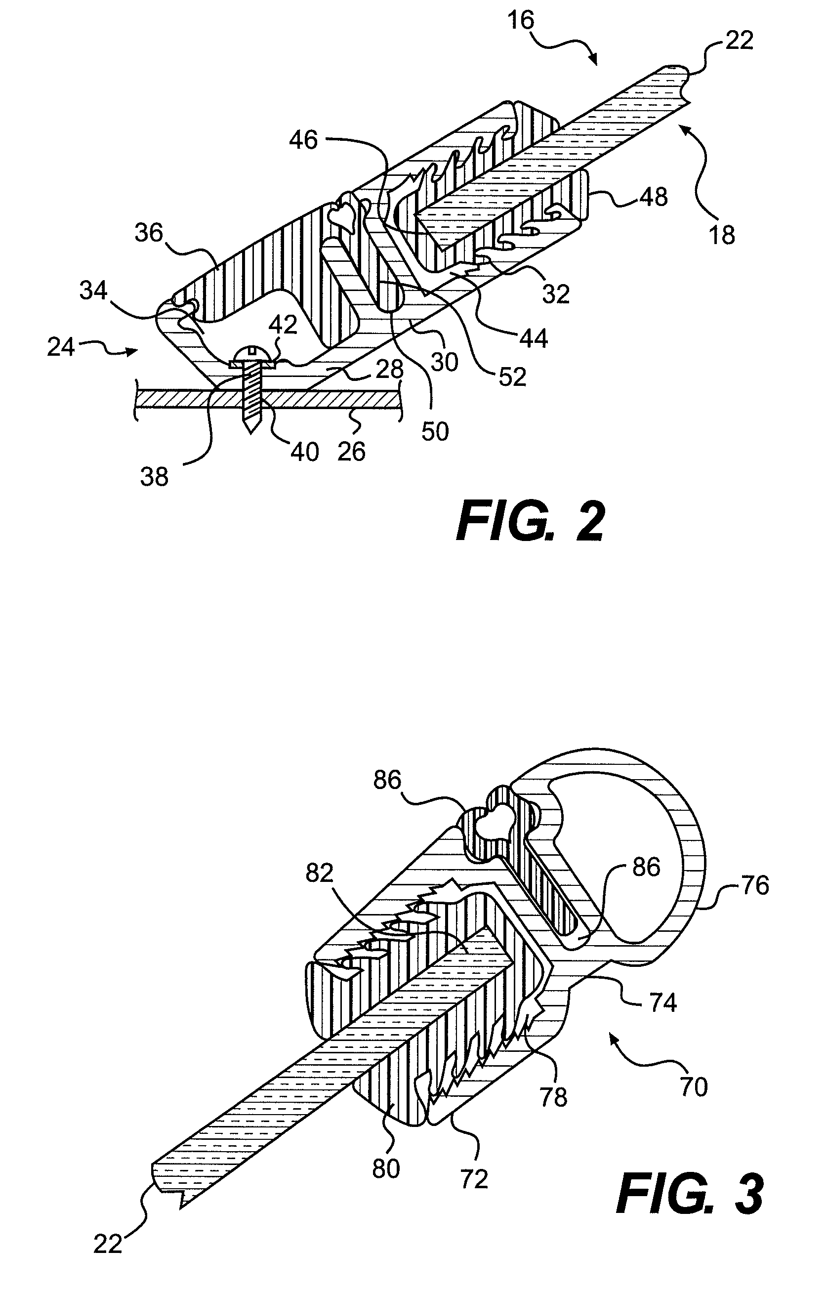
[0026]The bottom rail 24, at least in the illustrated embodiment is constructed from aluminum, largely because of aluminum's resistance to corrosion and its light weight. Of course, the bottom ra...


PUM


Abstract

A boat windshield is described including a transparent pane. A rail is disposed adjacent and secured to one of either the bottom or the top edge of the transparent pane. An opening is defined through the rail. An air intake housing is secured to the front surface of the rail. An air intake opening and passageway are defined in the air intake housing. An air discharge housing is secured to the rear surface of the rail. An air discharge opening and passageway are defined in the rear intake housing. The air intake passageway, the opening through the rail, and the air discharge passageway define an air pathway from the front surface to the rear surface of the rail. The air discharge opening is positioned adjacent to the rear surface of the transparent pane to direct air along the rear surface of the transparent pane upon exiting the air discharge housing.

Description

CROSS-REFERENCE TO RELATED APPLICATIONS[0001]This is a non-provisional patent application based upon and claiming the benefit of priority to U. S. Provisional Patent Application 60 / 978,664, filed on Oct. 9, 2007, the contents of which are incorporated herein by reference.FIELD OF THE INVENTION[0002]The invention relates to a vent for a windshield for a boat. In particular, the invention relates to a vent that permits air to be directed in a manner to reduce condensation of moisture, especially on the interior surface of the windshield.DESCRIPTION OF THE RELATED ART[0003]In the boating industry, it is common for a windshield to be mounted on the deck of a boat (or other suitable type of watercraft) without any provision for reducing the occurrence of condensate on the interior surface of the windshield.[0004]Unlike most automobiles, the cockpit of a medium-sized to large-sized boat typically is opened to the atmosphere (or to the environment). Typically, there is no provision for an ...

Claims


Application Information

Patent Timeline
Patent Type & Authority Applications(United States)
IPC IPC(8): B63B17/00B63J2/02B60H1/28
CPCB60H1/267B63J2/04B63B19/14B63B19/00
Inventor MASON, CHRISTOPHER A.WHITED, II, SHERMAN E.
Owner N A TAYLOR CO INC
Why Eureka
Try Eureka