Drive force distribution system for four wheel independent drive vehicle

a technology of drive force distribution and independent drive, which is applied in the direction of brake system, process and machine control, instruments, etc., can solve the problems of degrading the driving performance of the vehicle, changing the yaw moment about the center of gravity of the vehicle,

Inactive Publication Date: 2006-01-19
NISSAN MOTOR CO LTD
View PDF3 Cites 65 Cited by
  • Summary
  • Abstract
  • Description
  • Claims
  • Application Information

AI Technical Summary

Benefits of technology

[0006] The present invention was conceived in view of this problem of unintended changes in yaw moment. One object of the present invention is to provide a drive force distribution system for a four wheel independent drive vehicle that is capable of suppressing the changes in longitudinal and lateral accelerat

Problems solved by technology

Consequently, there are situations in which the lateral forces acting on the front wheels and the rear wheels change greatly when the revision is executed and cause the lateral acceleration to cha

Method used


Image

  • Drive force distribution system for four wheel independent drive vehicle
  • Drive force distribution system for four wheel independent drive vehicle
  • Drive force distribution system for four wheel independent drive vehicle

Examples


second embodiment

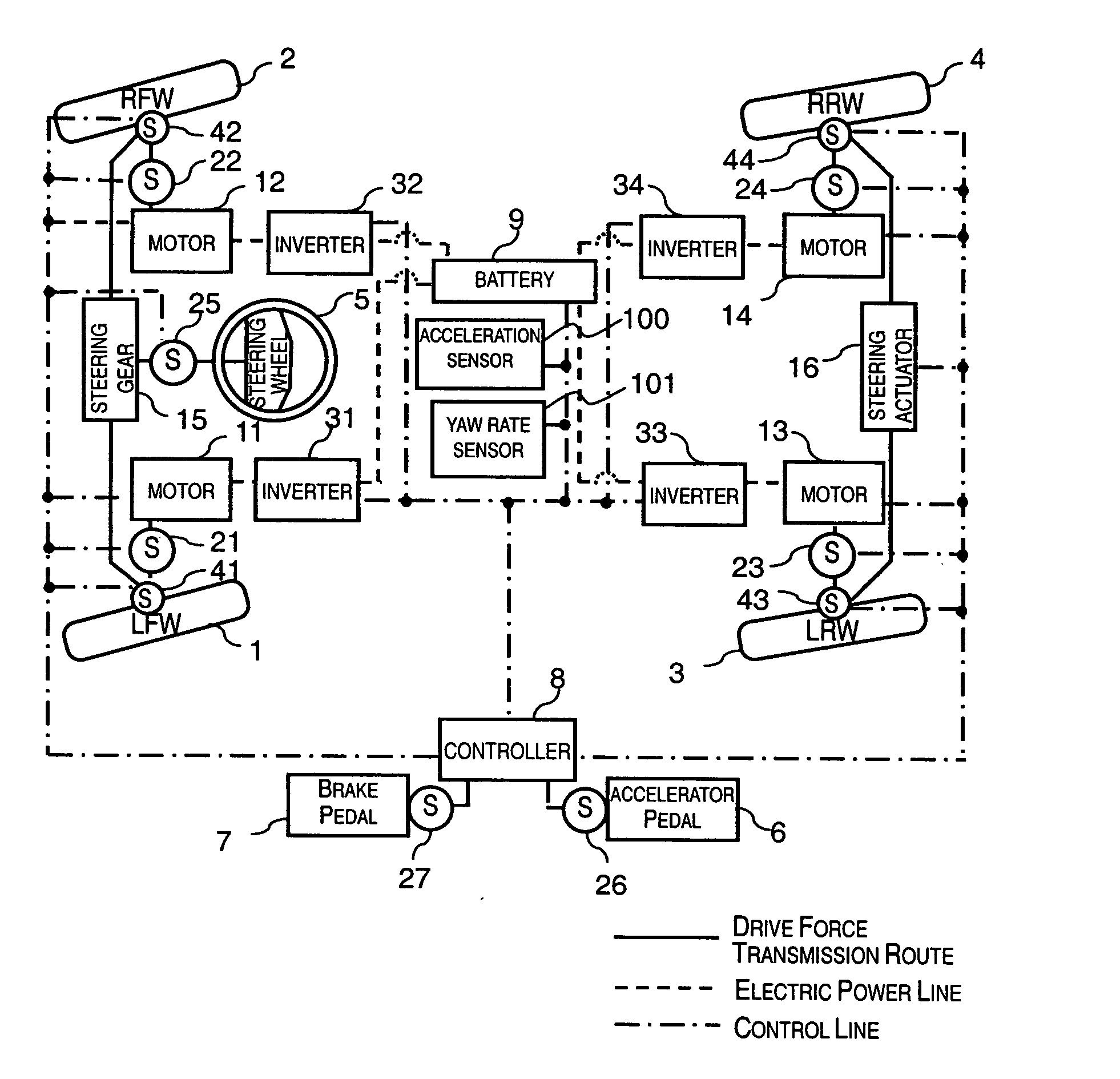
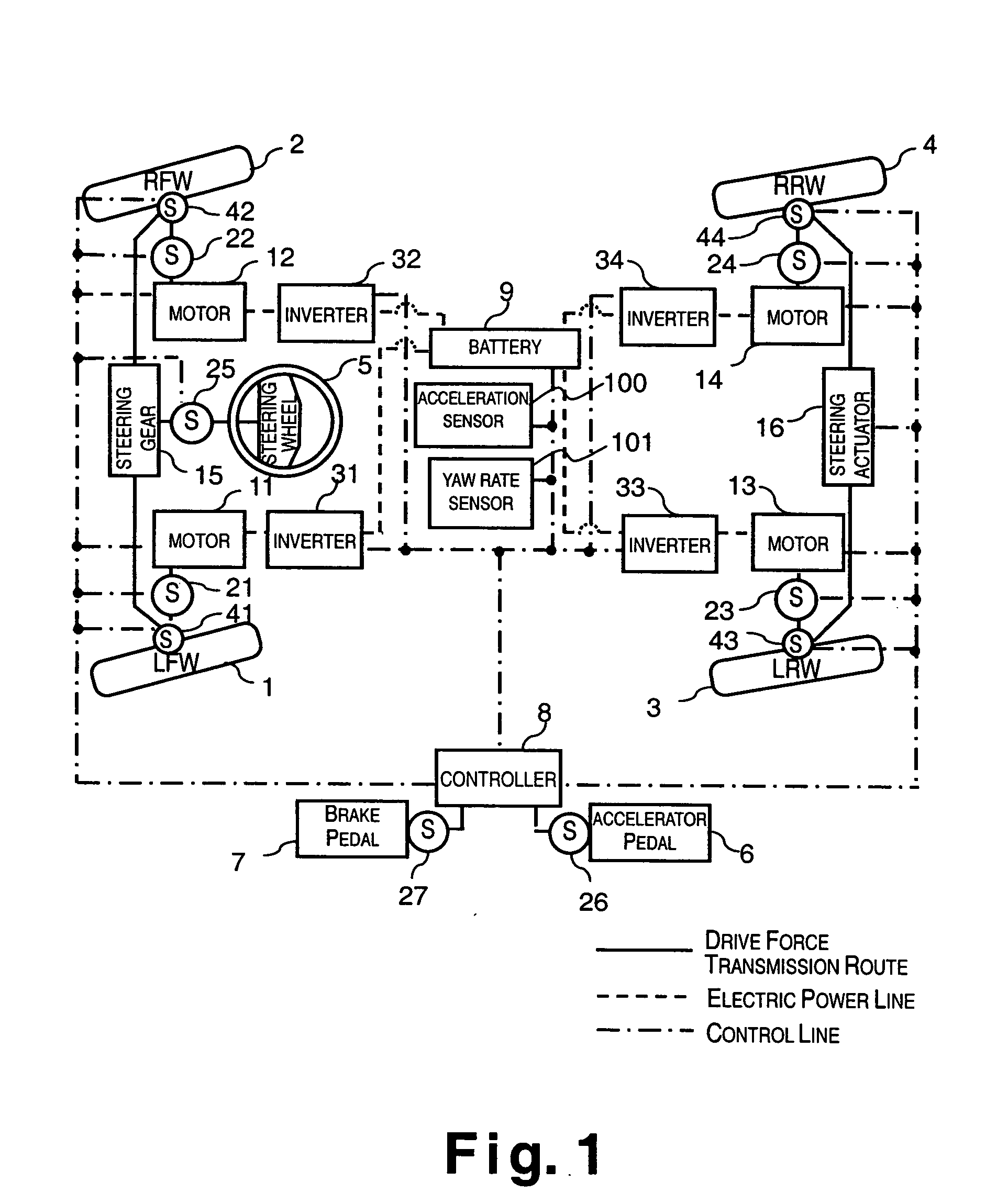
[0094] Referring now to FIG. 10, an alternate control program for the controller 8 of the vehicle schematically illustrated in FIG. 1 will now be discussed. Since only the programming is different between the first and second embodiments, the parts or steps of the second embodiment that are identical to the parts or steps of the first embodiment will be given the same reference numerals as the parts of the first embodiment. Moreover, the descriptions of the parts or steps of the second embodiment that are identical to the parts or steps of the first embodiment may be omitted for the sake of brevity. In other words, unless otherwise specified, the rest of the configuration of the vehicle in the second embodiment is the same as the configuration of the first embodiment.

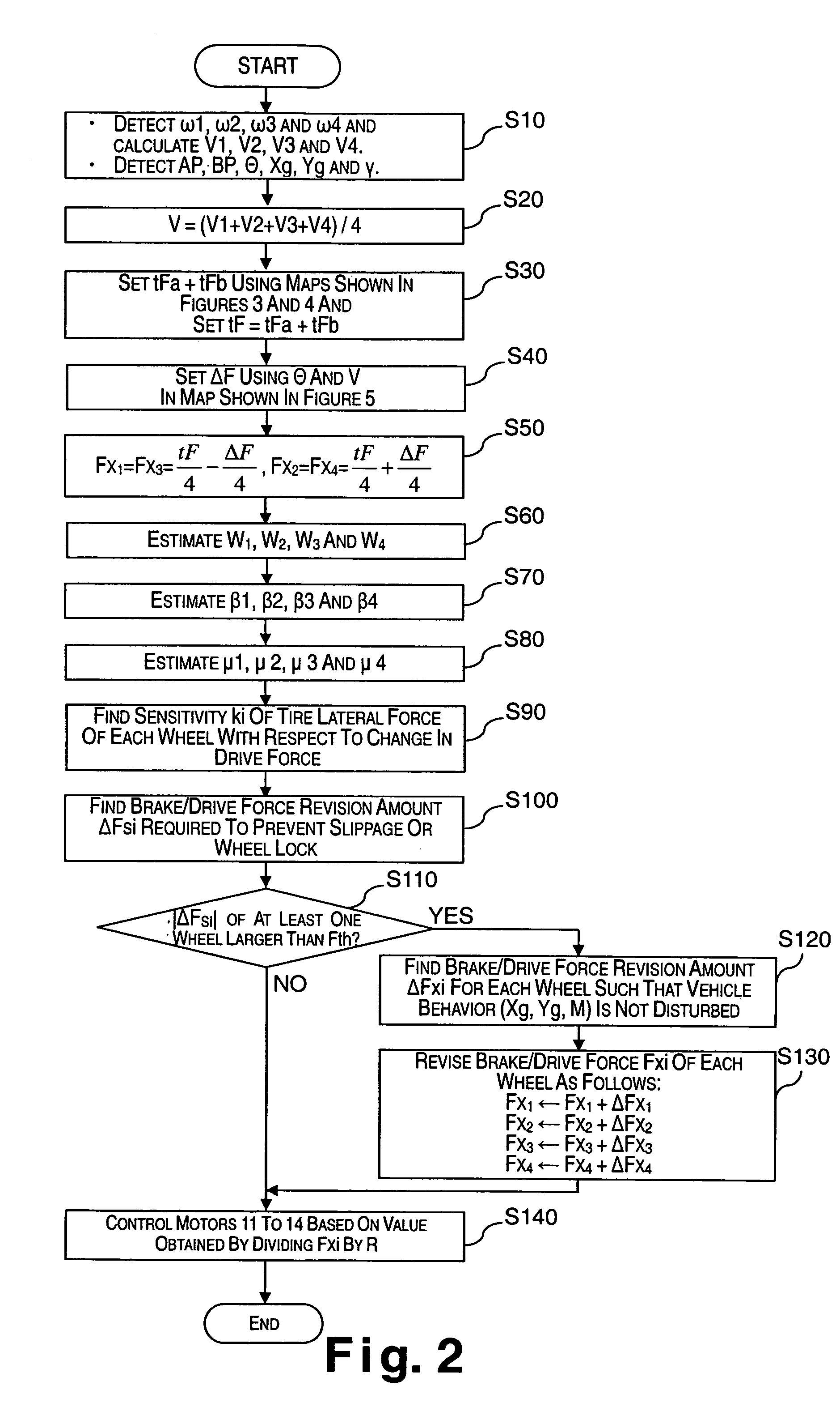
[0095]FIG. 10 illustrates a flowchart of the drive force distribution control executed by the controller 8 of the drive force distribution system in accordance with the second embodiment of the present invention. The f...

third embodiment

[0115] Referring now to FIGS. 11-17, an alternate control program for the controller 8 of the vehicle schematically illustrated in FIG. 1 will now be discussed. In this third embodiment, the drive force distribution system also uses the steering angles of the wheels 1 to 4 in revising the brake / drive forces applied the wheels 1 to 4.

[0116] Since only the programming is different between this third embodiment and the prior embodiments, the parts or steps of the second embodiment that are identical to the parts or steps of the first embodiment will be given the same reference numerals as the parts of the first embodiment. Moreover, the descriptions of the parts or steps of the third embodiment that are identical to the parts or steps of the prior embodiments may be omitted for the sake of brevity. In other words, unless otherwise specified, the rest of the configuration of the vehicle in the third embodiment is the same as the configuration of the prior embodiments.

[0117] With this ...


PUM


Abstract

A drive force distribution system for a four wheel independent drive vehicle is configured to suppress changes in longitudinal and lateral accelerations and change in yaw moment about the center of gravity of the vehicle that occur when the brake/drive force of one wheel changes or is changed deliberately. The drive force distribution system is configured such that when the brake forces and the drive forces determined by the brake/drive force determining section based on the motion requirements of the vehicle are to be changed, the drive force revising section revises the brake/drive forces of the left front wheel, the right front wheel, the left rear wheel, and the right rear wheel by amounts, respectively, based on the sensitivities of the tire lateral forces of each of the wheels estimated by the tire lateral force sensitivity estimating section so as to satisfy the motion requirements of the vehicle.

Description

CROSS-REFERENCE TO RELATED APPLICATIONS [0001] This application claims priority to Japanese Patent Application Nos. 2004-205689 and 2004-280139. The entire disclosures of Japanese Patent Application Nos. 2004-205689 and 2004-280139 are hereby incorporated herein by reference. FIELD OF THE INVENTION [0002] The present invention generally relates to a drive force distribution system. More specifically, the present invention relates to a drive force distribution system for a four wheel independent drive vehicle equipped with a separate drive motor for each drive wheel of the four wheel drive vehicle. BACKGROUND INFORMATION [0003] An example of a conventional drive force distribution system is disclosed in Japanese Laid-Open Patent Publication No. 10-295004. The drive force distribution system described in this publication is used for controlling a four wheel independent drive vehicle that is equipped with a separate drive motor for each drive wheel of the four wheel drive vehicle. With...

Claims


Application Information

Patent Timeline
IPC IPC(8): B60K17/356
CPCB60K7/0007B60K17/356B60K17/358B60W2550/148B60T8/1769B60W2520/26B60W2530/10B60K23/0808B60W2552/40
Inventor YAMAGUCHI, ICHIRODEGUCHI, YOSHITAKAINOUE, HIDEAKI
Owner NISSAN MOTOR CO LTD
Why Eureka
Try Eureka