Measuring equipment and method for mapping the geology in an underground formation

a geological and underground formation technology, applied in geological measurements, seismology, reradiation, etc., can solve the problems of inability to use instruments for mapping ground-water resources, inconvenient use of measuring equipment, and difficulty in accurately compensating or correcting these influences, so as to achieve advantageously reduce the size of the transmitter coil of the measuring equipment and the effect of large magnetic momen

Active Publication Date: 2006-01-19
BUBIOIL
View PDF8 Cites 27 Cited by
  • Summary
  • Abstract
  • Description
  • Claims
  • Application Information

AI Technical Summary

Benefits of technology

[0027] By placing several transmitter coils each controlled by its own transmitter above the structure, a total large magnetic moment can advantageously be transmitted simultaneously with the transmitting current in each single transmitter coil relatively quick can be cut off. Also, by placing the transmitter coils closely above each other on the same plane, it is advantageously obtained that they perform as one transmitter coil and thus total have an area which has a common tangent on the same plane as the transmitter coils. By closely above each other, it should in this context be understood that the transmitter coils in their entirety are placed closely above each other or that their turns are placed closely above each other.
[0028] Furthermore the number of turns in the separate coils can be changed for thereby obtaining different magnetic moments and turn off time for the transmitting currents. The at least one transmitter coil of the measuring equipment can according to the invention be arranged to also transmit magnetic moments of different sizes, whereby different decaying times can be measured. In an advantageous embodiment the wire of the transmitter coil can consist of a number of electrically insulated cores. Thereby the thick thread effect which is created at large currents and which could interfere with the measurements to a considerable degree is eliminated.
[0029] According to the invention the size of the transmitter coil of the measuring equipment can advantageously be reduced from e.g. 40×40 meter of the known transmitter coil to, for example, a compact transmitter coil of 10×10 meters. When laying out on the ground, it is advantageously obtained that the compact transmitter coil according to the invention can be transported and laid out far easier than the large transmitter coils conventionally used. In the compact transmitter coil it will be possible to transmit large moments as in the conventionally used large transmitter coils whereby noise from the surroundings will interfere with the measurements to a lesser degree.

Problems solved by technology

It is very difficult to compensate or correct precisely enough for these influences.
The instruments can however not be used for mapping of ground-water resources since in these cases, it is necessary to acquire a considerably more detailed and accurate knowledge of the decay signal at both late and early decay times.
Because of crops in the fields and soft ground especially in the spring and autumn seasons there are furthermore long periods of time when it is not possible to conduct sounding in the fields.
Even though this method is effective and reliable, it is not optimal for e.g. airborne transient sounding where the mechanical construction, such as size and reduction of coupling between transmitter and receiver, is very important.
The technique known from the above U.S. Pat. No. 3,835,371, which operates with coils that are perpendicular to each other, is close to useless for transient sounding which works with parallel coils.
This solution cannot be used, however, for measurement of earth responses from transient fields which are obtained by a quick cut-off of the current.
The cut-off time in the two coils is thus not identical, resulting in the generated magnetic fields being unable to even out each other in the middle of the coils.

Method used


Image

  • Measuring equipment and method for mapping the geology in an underground formation
  • Measuring equipment and method for mapping the geology in an underground formation
  • Measuring equipment and method for mapping the geology in an underground formation

Examples


Embodiment Construction

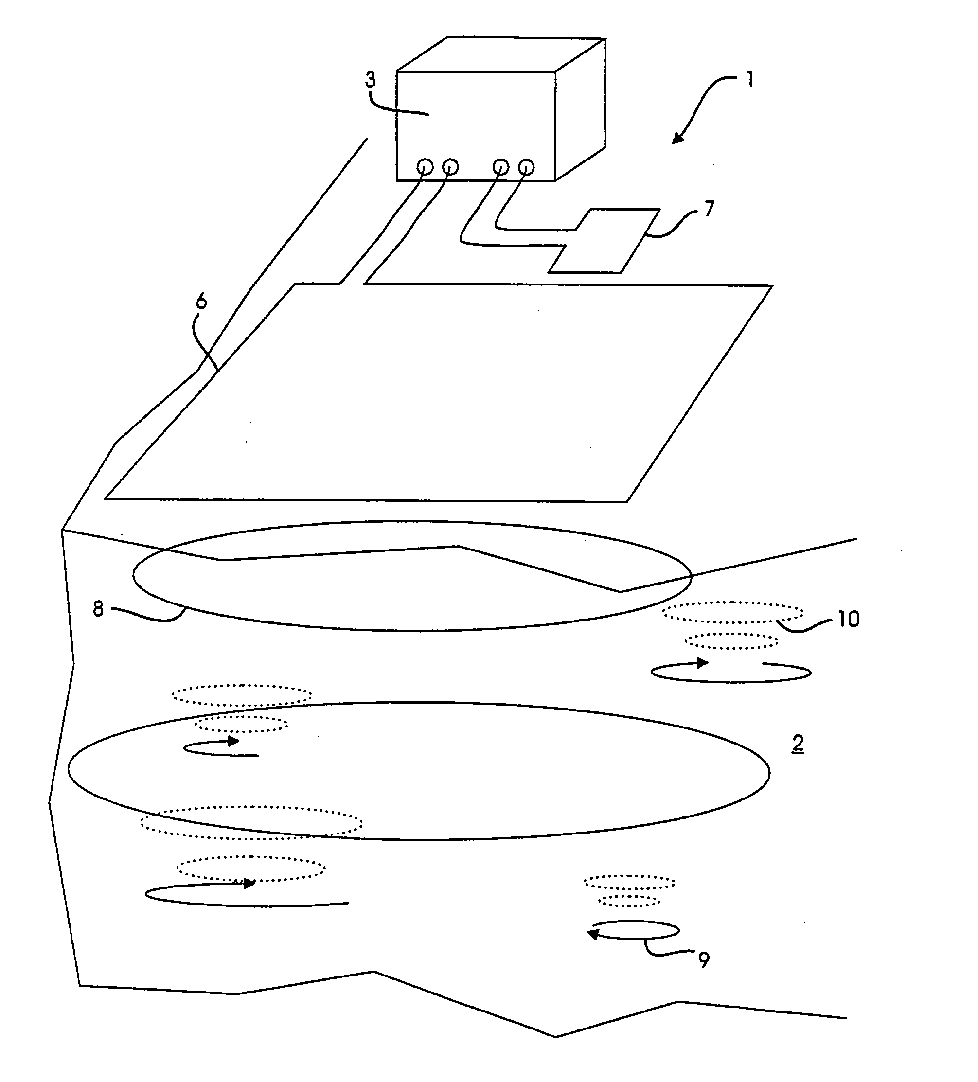
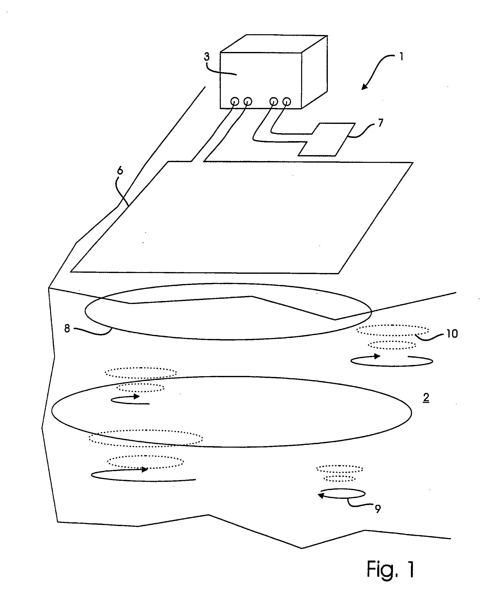
[0055]FIG. 1 shows measuring equipment 1 for mapping the geology in an underground formation 2. The measuring equipment comprises a cabinet 3 with a part of a transmitter circuit 4 and a receiving circuit 5 (shown in FIGS. 2, 3 and 4). A transmitter coil 6 belonging to the transmitter circuit and a receiving coil 7 belonging to the receiving circuit are placed outside the cabinet.

[0056] When a transmitting current IT is transmitted through the transmitter coil 6, a primary magnetic field is built up in the formation 2. By subsequently cutting off the current, the magnetic field will decay whereby eddy currents are formed in the formation, which build up a secondary magnetic field 10 which induces an electrical current in the receiving coil 7. The primary magnetic field, which still exists until the current in the transmitter coil has decreased to zero, simultaneously induces an electrical current in the receiving coil 7.

[0057] This current is registered as a receiving voltage over...


PUM


Abstract

The invention relates to measuring equipment and method for mapping the geology in an underground formation by means of transient electromagnetic sounding. The measuring equipment includes a transmitter circuit with a current source for generating an electric current and a transmitter coil; a switch for connecting the current source to the transmitter coil during operation so that an electric current is generated in it, with the current building up a magnetic field in the formation, and for cutting off this current again so that the built-up magnetic field in the formation decays; and a receiving circuit with a receiving coil for registering the voltage induced over the receiving coil. By placing the receiving coil in an area where the magnetic field strength is small, the transmitter coils placed closely above each other, the wire of the transmitter coil is composed of a number of electrically insulated cores, and there is a preamplifier for amplifying the registered voltage (VRcoil) from the receiving coil and the second electrical switch for disconnecting the connection between the receiving coil and the preamplifier, a measuring equipment can be provided that is so compact that it can be used for airborne transient sounding.

Description

CROSS-REFERENCE TO RELATED APPLICATION [0001] This application is a continuation of International application PCT / DK2004 / 000102 filed Feb. 13, 2004, the entire content of which is expressly incorporated herein by reference. BACKGROUND ART [0002] The invention relates to a measuring equipment and a method for mapping the geology in an underground formation and which comprises at least one transmitter circuit with at least one transmitter coil and a current source, at least one switch inserted between the current source and the at least one transmitter coil and which during operation serves to connect the current source of the at least one transmitter circuit with the at least one transmitter coil to generate an electrical current for building up a magnetic field in the formation and to break the electrical current again to thereby cause the built-up magnetic field in the formation to decay, and at least one receiving circuit with at least one receiving coil to measure the decay signa...

Claims


Application Information

Patent Timeline
Patent Type & Authority Applications(United States)
IPC IPC(8): G01V3/38G01V1/00G01V3/00G01V3/12
CPCG01V3/12G01V3/107
Inventor SORENSEN, KURT I.
Owner BUBIOIL
Why Eureka
Try Eureka