Swimming pool drain

a technology for draining pools and swimming pools, applied in the direction of gyms, buildings, construction, etc., can solve the problems of high risk of drowning, inability to extract, and high health hazards of users of pools or spas, and achieve the effect of low velocity and high volum

a technology for draining pools and swimming pools, applied in the direction of gyms, buildings, construction, etc., can solve the problems of high risk of drowning, inability to extract, and high health hazards of users of pools or spas, and achieve the effect of low velocity and high volum

US20060015996A1Inactive Publication Date: 2006-01-26GSG HLDG

Image

  • Swimming pool drain
  • Swimming pool drain
  • Swimming pool drain

Examples


Embodiment Construction

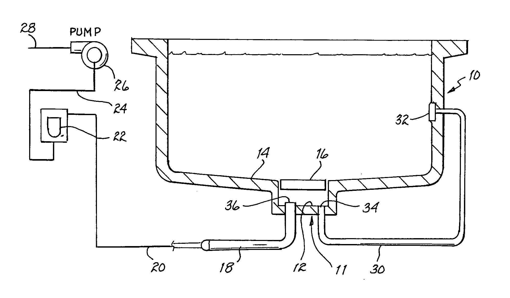
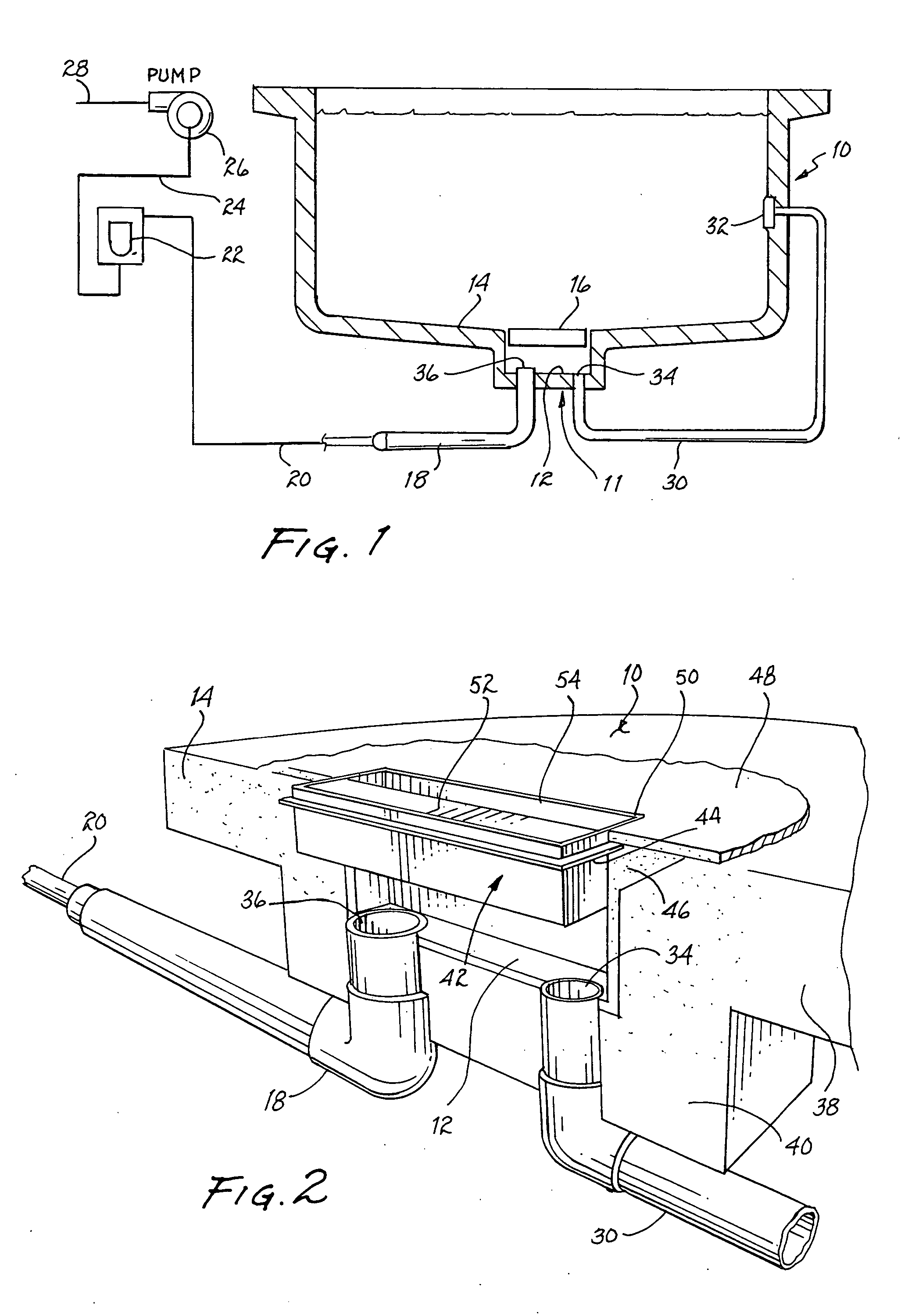
[0066] Referring to FIG. 1, there is illustrated a representative cross section of a swimming pool 10 having drain 11. The drain is formed in the cementitious material defining the pool and includes a sump 12 generally located at the low spot in bottom 14 of the pool. It is to be understood that the drain may be elsewhere in the bottom or in a wall of the pool or a spa. While the discussion below is primarily directed to various sumps useable in swimming pools, these sumps could also be used in spas and the like. A preformed grate 16 is disposed and retained at the inlet to the sump and incorporates one or more, but preferably one aperture for inflow of water to the sump. A suction line 18 of relatively substantial diameter extends from sump 12. It is connected to a conventionally sized suction line 20 in fluid communication with a conventional debris trap 22. A further suction 24 extends from the debris trap to the inlet in pump 26. Outflow from the pump through return line 28 is c...


PUM


Abstract

A sump for a swimming pool or spa includes a grate having an elongated slot for inflow of water at a low velocity high flow rate. A housing of relatively large capacity includes an outlet for conveying water to an oversized suction line to maintain the low velocity high flow rate to the junction with a conventionally sized standard suction line in fluid communication with a suction pump. A bypass line in fluid communication with the water in the pool or spa discharges water into the housing when the slot is sufficiently covered to prevent satisfying the flow rate into the suction line demanded by the pump and thereby prevent a level of suction at the slot sufficient to entrap clothing or a body part of a swimmer against the grate. The grate, a frame supporting the grate on the housing and the housing are devoid of elements that might cause entanglement of hair drawn into the sump. A hydrostatic valve may be coupled with the housing at locations of a pool or spa where the ground water level is sufficiently high to cause flotation of the pool or spa when partially filled or empty.

Description

CROSS REFERENCE TO RELATED APPLICATIONS [0001] The present application is related to the swimming pool drain disclosed in U.S. patent application entitled ā€œPOOL FLOOR DRAIN ASSEMBLY FOR A SUCTION-ACTIVATED WATER CIRCULATION SYSTEMā€, assigned Ser. No. 10 / 144,899 and filed May 14, 2002, which application is incorporated by reference herein.BACKGROUND OF THE INVENTION [0002] 1. Field of the Invention [0003] The present invention relates to drains for swimming pools and, more particularly to drains that will not permit entrapment of persons, their clothing or their hair thereagainst. [0004] 2. Description of Related Art [0005] Most swimming pools and spas, whether of concrete / gunite, fiberglass or having a vinyl liner above ground or in ground, include a drain at the lowest point. The purpose of the drain is to provide an outlet for flow of water from the swimming pool to the suction side of a pump. The outflow of the pump is passed through a filter to remove entrained matter. The filte...

Claims


Application Information

Patent Timeline
26 Jan 2006
Publication
US20060015996A1
IPC
E04H4/00
CPC
E04H4/12; E04H4/1236
Inventors
GOETTL, JOHN M.