

Slide fastener stringer and method of manufacturing the same
a technology of slide fasteners and stringers, which is applied in the direction of slide fasteners, press-button fasteners, and paper clips, etc., can solve the problems of long time, complicated procedures and processes, and achieve the effect of easy manufacturing
- Summary
- Abstract
- Description
- Claims
- Application Information
AI Technical Summary
Benefits of technology
Problems solved by technology
Method used
Image

Examples
first embodiment
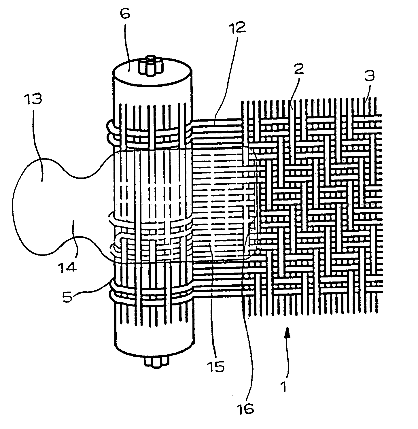
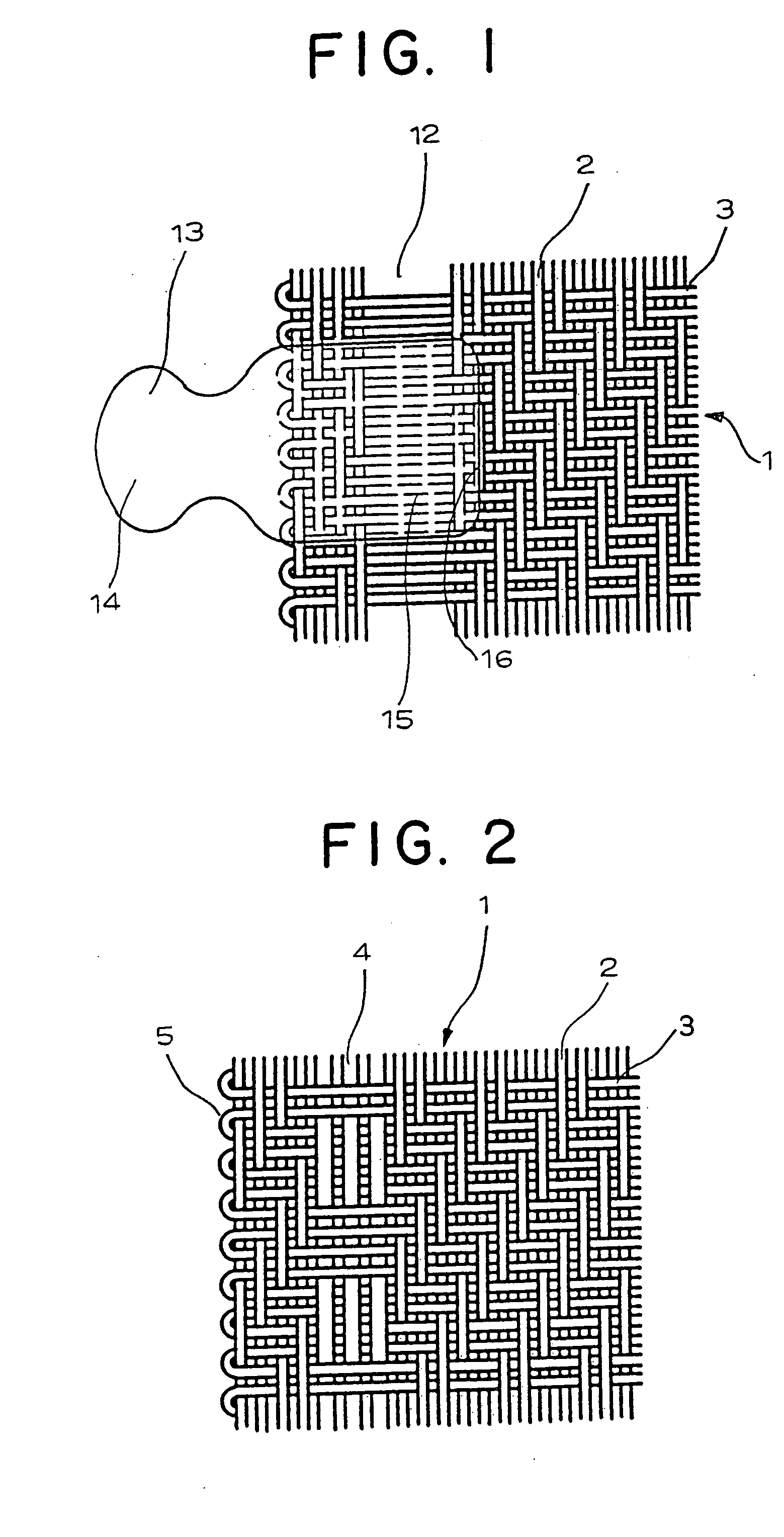
[0035] A slide fastener stringer of a first embodiment of the present invention shown in FIG. 1 is woven with warp yarns 2 and weft yarns 3 formed of multi-filament yarns of polyester fiber or polyamide fiber. The fastener tape 1 is produced by needle weaving with the weft yarn 3 by double picks. In the fastener tape 1, a warp yarn exclusion area 12, in which only the weft yarns 3 exist, is provided inside of plural pieces of the warp yarns 2 placed along a side edge 5 by removing plural pieces of the warp yarns 2. Fastener elements 13 having an appropriate shape are injection molded in the warp yarn exclusion area 12 by using such thermoplastic resin as polyacetal and polyamide. A coupling head 14 of the fastener element 13 is projected outward from the side edge 5 of the fastener tape 1, and the leg 15 or a front end portion 16 of the leg is formed so as to adhere to the weft yarn 3 existing in the warp yarn exclusion area 12 and the warp yarn 2 facing the warp yarn exclusion area...
second embodiment
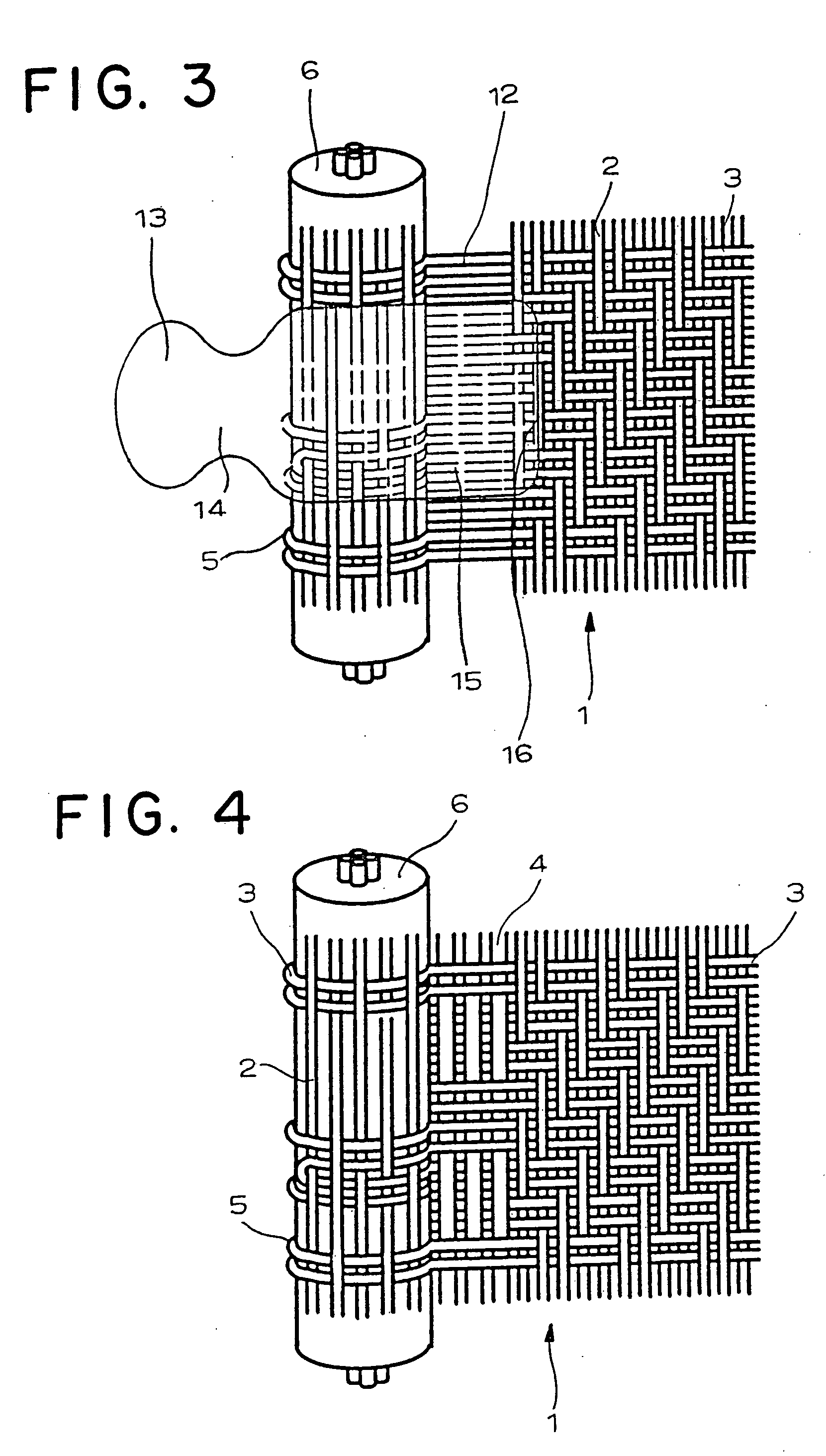
[0037] A slide fastener stringer of a second embodiment of the present invention shown in FIG. 3 is woven with warp yarns 2 and weft yarns 3 formed of multi-filament yarns of polyester fiber or polyamide fiber. The fastener tape 1 is produced by needle weaving by double pick with the weft yarn 3, and a core thread 6 having a large diameter is woven into a side edge 5 of the fastener tape 1. As the core thread 6, several pieces of multi-filament yarns of polyester fiber or polyamide fiber are used, and the same kind of the multi-filament yarn is braided around it to produce the core thread 6. A warp yarn exclusion area 12 in which only the weft yarns 3 exist is provided at a portion corresponding to plural pieces of the warp yarns 2 adjacent to the core thread 6 in the fastener tape 1. Fastener elements 13 of an appropriate shape are injection molded in the warp yarn exclusion area 12 by using such thermoplastic resin as polyacetal and polyamide.
[0038] A coupling head 14 of the fast...
third embodiment
[0039] A slide fastener stringer of a third embodiment of the present invention shown in FIG. 5 is woven with warp yarns 2 and weft yarns 3 formed of multi-filament yarns of polyester fiber or polyamide fiber. The fastener tape 1 is produced by needle weaving by double picks with the weft yarns 3, and a core thread 6 having a small diameter is woven into a side edge 5 on both the front and rear surfaces of the fastener tape 1. As the core thread 6, a single piece of multi-filament yarn of polyester fiber or polyamide fiber is used, and the same kind of the multi-filament yarn is braided around it so as to produce the core thread 6. In the fastener tape 1, the warp yarns 2 are disposed adjacent to the core thread 6, and then, the warp yarn exclusion area 12 in which only the weft yarns 3 exist is provided at a portion corresponding to plural pieces of the warp yarns 2 adjacent to these warp yarns 2. Then, fastener elements 13 of an appropriate shape are injection molded in the warp y...
PUM
 Abstract
Description
Claims
Application Information