Self-piercing rivet fastening device with improved die

Inactive Publication Date: 2006-01-26
NEWFREY
View PDF7 Cites 9 Cited by
  • Summary
  • Abstract
  • Description
  • Claims
  • Application Information

AI Technical Summary

Benefits of technology

[0008] The present inventor conducted several studies to determine why holes are opened by legs of self-piercing rivets. Dies have a cavity for receiving a portion of fastened components forced outward by a self-piercing rivet driven in by a punch. The single cause of hole opening was found to be slippage between a fastened component and the cavity surface in the die when a fastened component driven by the punch was pushed into the die and deformed inside the cavity. The tips of the spread legs of a self-piercing rivet are especially likely to break through and form holes when the fastened component adjacent to the die is a body panel with press molding oil adhering to it. This causes the body panel to easily slip inside the die cavity, so that proper leg deformation does not occur.
[0009] The aforesaid U.S. Pat. No. 5,752,305 discloses a self-piercing riveting method and apparatus in which a punch of a riveting tool is surrounded by a preclamping element having an annular clamping surface for urging two overlapping sheets against a die. The annular clamping surface may have a rough finish provided, for example, by knurling or annular grooving in order to improve the grip on the sheet material and prevent material being pulled laterally into the joint. A coining ring may be provided on the annular clamping surface to prevent material flow and to regulate distortion adjacent to the rivet head. The self-piercing riveting method and apparatus uses a die having an annular clamping surface which may be roughened in the same way as the annular clamping surface of the punch preclamping element.
[0010] The present inventor discovered that roughening particular surface portions of the die cavity is effective in preventing legs of a self-pierc

Problems solved by technology

The single cause of hole opening was found to be slippage between a fastened component and the cavity surface in the die when a fastened component driven by the punch was pushed into the die and deformed inside the

Method used


Image

  • Self-piercing rivet fastening device with improved die
  • Self-piercing rivet fastening device with improved die
  • Self-piercing rivet fastening device with improved die

Examples


Example

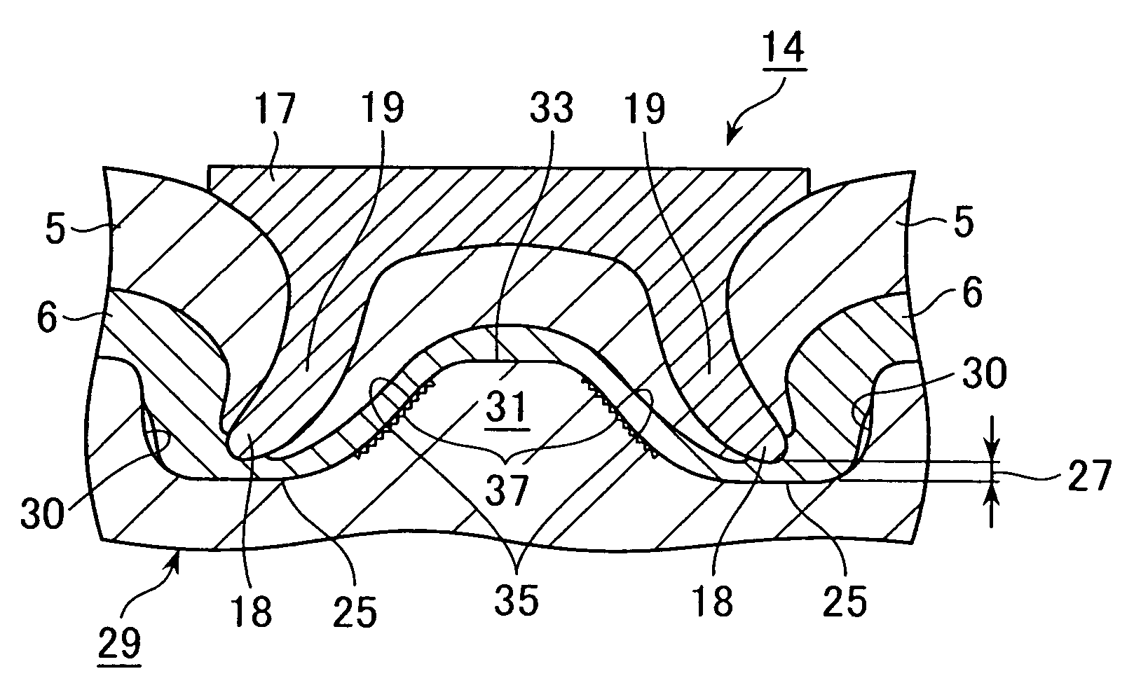
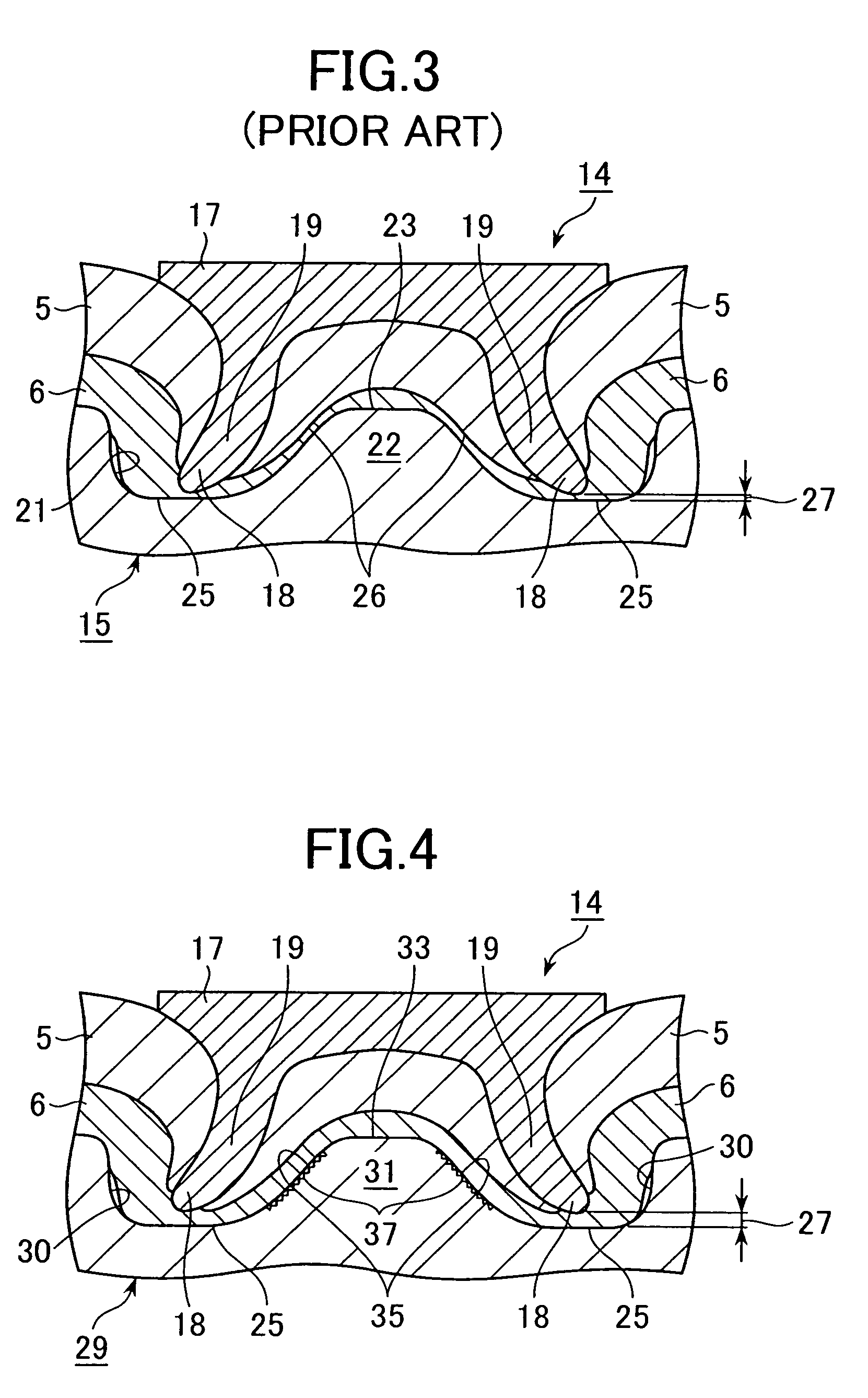
[0026] A die in an embodiment of a self-piercing rivet fastening device of the present invention will now be explained with reference to FIG. 4 through FIG. 10 and in comparison to a die of the prior art. In FIG. 3, 14 denotes a conventional self-piercing rivet and 15 denotes a die of the prior art. The self-piercing rivet 14 has a head 17 and legs 19 whose tips 18 become deformed when driven into components 5, 6 by a punch (not shown) so as to spread the legs outward radially. The die 15, which may be made of tool steel, for example, has a cavity 21 for receiving portions of the fastened components 5, 6 forced outward by the legs 19 of the self-piercing rivet 14 driven in by the punch. The cavity 21 has a protrusion 22 at its center protruding towards the punch. The protrusion 22 has a substantially flat top 23 and an inclined surface portion 26 between the top 23 and the bottom surface 25 of the cavity. The inside surface of the cavity 21, the top 23 of the protrusion 22, the incl...


PUM

PropertyMeasurementUnit
Frictionaaaaaaaaaa

Abstract

A self-piercing rivet fastening device has a punch that drives legs of the rivet into portions of workpieces that are forced into a die cavity, in order to join the workpieces. Particular surfaces of the die cavity are modified to increase the coefficient of friction in order to prevent tips of the legs of the rivet from breaking through a workpiece adjacent to the die and forming holes.

Description

CROSS-REFERENCE TO RELATED APPLICATION [0001] This application claims the benefit of Japanese Application No. 2004-200542 filed Jul. 7, 2004, incorporated herein by reference. BACKGROUND OF THE INVENTION [0002] The present invention relates to a device for driving a self-piercing rivet into a plurality of components to be fastened, and more particularly to an improved die from such a device. [0003] Self-piercing rivets are frequently used to fasten together aluminum body panels that are unfit for welding. Automotive panels are increasingly being made of aluminum to reduce the overall weight of automobiles, and demand for self-piercing rivets is growing. [0004] An example of a self-piercing rivet fastening device is described in U.S. Pat. No. 5,752,305 issued May 19, 1998, corresponding to Japanese Examined Patent Application Publication No. 8-505087 (Patent Document 1). FIG. 1 and FIG. 2 are drawings of the self-piercing rivet fastening device described in Patent Document 1, and of ...

Claims


Application Information

Patent Timeline
IPC IPC(8): B21J15/00
CPCB21J15/025B21J15/36Y10T29/5343Y10T29/5118Y10T29/49837Y10T29/49956Y10T29/5377Y10T29/53991
Inventor KATO, TORU
Owner NEWFREY
Why Eureka
Try Eureka