
Fishing lure and kit

a technology for fishing lures and lures, applied in fishing, other angling devices, animal husbandry, etc., can solve the problems of wasting time, consuming valuable time, reattaching lines and unhooking fish, etc., and achieve the effect of easy removal and replacemen

Active Publication Date: 2006-01-26
ZUK ANDREW
View PDF103 Cites 28 Cited by
  • Summary
  • Abstract
  • Description
  • Claims
  • Application Information

AI Technical Summary

Benefits of technology

[0013] Embodiments include a tail that is capable of releasing a drag chute when struck by a fish, capable of slowing the progress of a running fish, while facilitating reeling-in the fish.
[0014] Embodiments include dive wings, fastened to removable tails, capable of causing a lure to achieve a desired depth when pulled through water.
[0015] Embodiments for example those fashioned of 6061 aluminum and / or stainless steel, are environmentally sound, durable, and corrosion resistant.
[0017] Various embodiments facilitate effective and efficient fishing in numerous applications (e.g., trolling, jogging, casting, sliding, bottom bouncing), and are capable of working in different rigging configurations (e.g., arm lure, teaser). Removable tails save time by providing quick disconnect and reconnect, only requiring seconds to change weight, color, form, and / or function on a single line, thus increasing fishing productivity. Space is saved because fewer units are required and many interchangeable components can be stored in one box. Consumers save money by replacing many single-use and / or single-function fishing devices with fewer components. Such lure kits are also versatile and fun for users; use being easily learned.

Problems solved by technology

Reattaching lines and unhooking fish are time-consuming processes that waste time during the important interval while fish are hitting.
Another problem with typical fishing lures is that it is desirable to change lures to ones of different shape, color, pattern, weight, depth or other features quickly, while fish are hitting other lines.
Lures that are tied on need to be cut, and new lures re-tied, thus consuming valuable time.
Also, because the design or function of each lure is a permanent part of the lure body, it can be necessary to purchase and carry a large collection of complete lures, expending money and being burdensome.

Method used


Image

  • Fishing lure and kit
  • Fishing lure and kit
  • Fishing lure and kit

Examples


Embodiment Construction

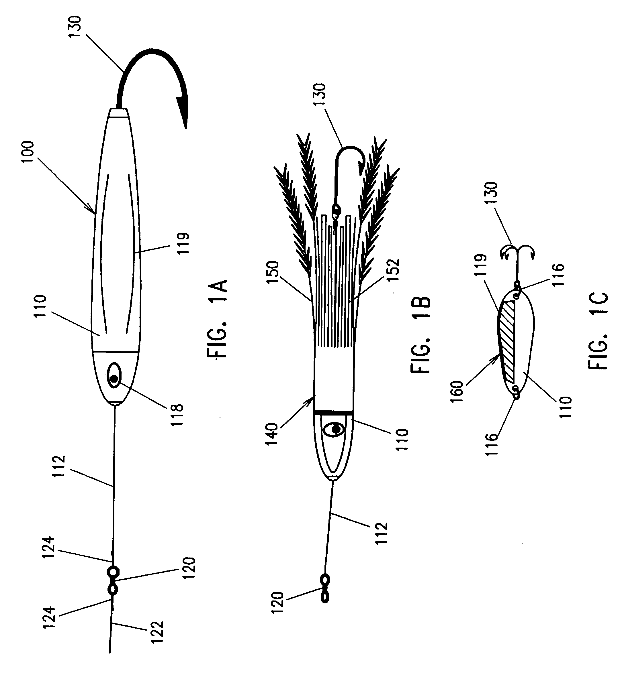
[0018]FIGS. 1A, 1B, and 1C (prior art) are plan views of typical fishing lures and lines.

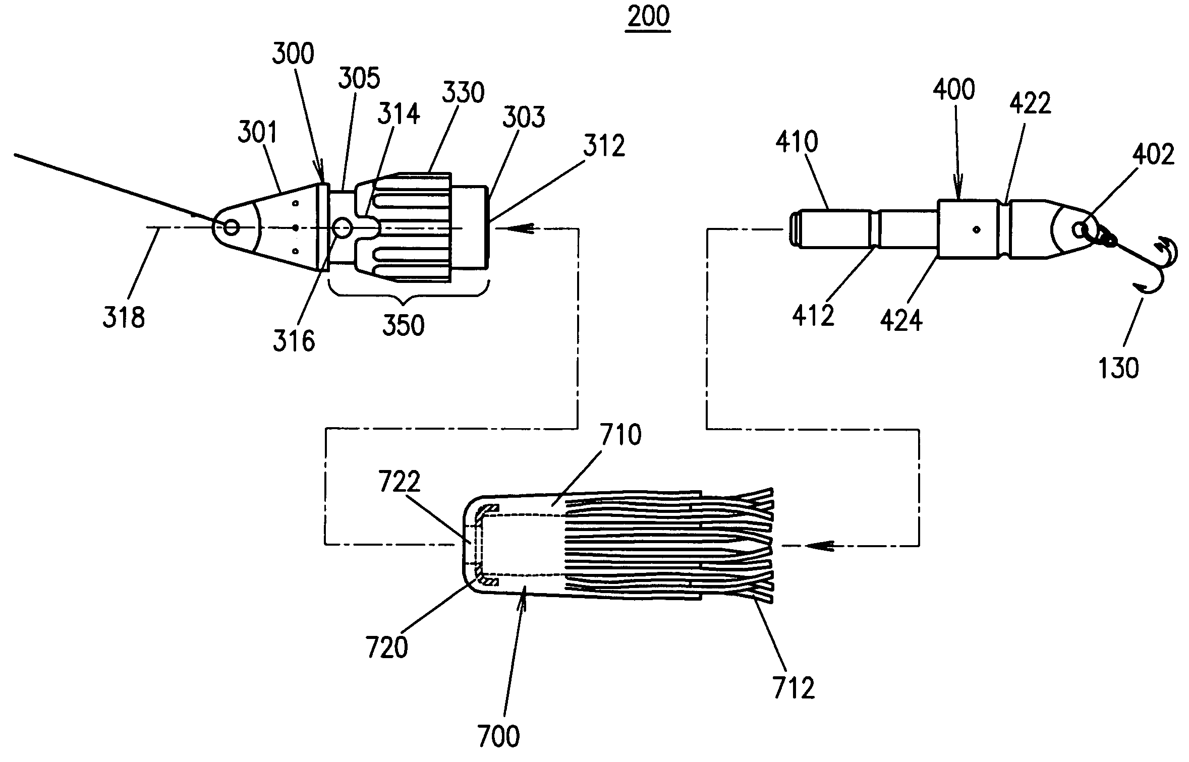
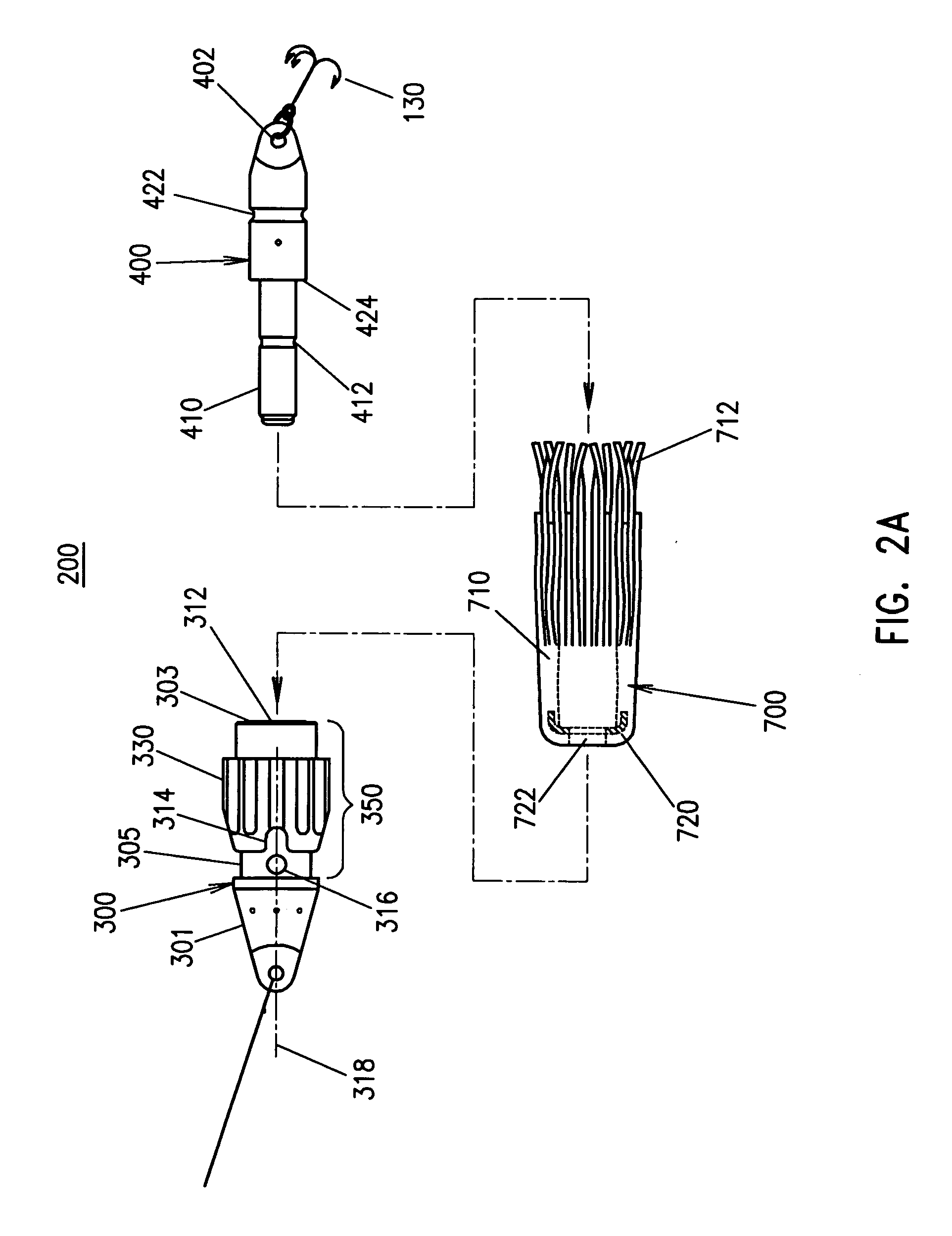
[0019]FIG. 2A is a partially exploded view of an embodiment of a fishing lure, according to the present invention.

[0020]FIG. 2B is an assembled view of an embodiment of a fishing lure, according to the present invention.

[0021] FIGS. 3A, 3A1, and 3A2 are sides end, and cut views of an embodiment of a lure head with a quick release mechanism, according to the present invention.

[0022]FIG. 3B is a plan view, from a rotated perspective, of an embodiment of a lure head core, according to the present invention.

[0023]FIG. 3C is a view along cut line 3C of an embodiment of a head core and bearings, according to the present invention.

[0024]FIG. 3D is a partial sectional view of an embodiment of a quick release mechanism, according to the present invention

[0025]FIG. 3E is a partial sectional view of an embodiment of a locking mechanism, rotated 90 degrees from FIG. 3D, according to the present inven...


PUM


Abstract

A fishing lure is described, having a head with a release mechanism and a removable tail. Because the tail can be released, fish caught on hooks can be released quickly, and new tails with new hooks rapidly attached to the same head. Multiple tails may be equipped with different lure skirts, for different fish and / or different conditions, and rapidly changed out in the course of fishing. A tail including a drag chute released by a fish strike, attachable to the same head, is also disclosed. A dive wing, attachable to the removable tails, is also disclosed. Tails can include bait scent chambers and release holes and water jets to attract fish. A kit with combinations of heads, tails, dive wings, and other parts and accessories is also disclosed.

Description

CROSS-REFERENCE TO RELATED APPLICATIONS [0001] This application claims priority from U.S. Provisional Patent Application No. 60 / 591,249, filed Jul. 26, 2004, entitled Fishing Lure and Kit, to inventor Andrew Zuk, the contents of which are incorporated by reference herein in their entirety.FIELD OF THE INVENTION [0002] 1. Field [0003] Embodiments relate to the field of sporting equipment, and in particular, fishing lures. [0004] 2. Related Art [0005]FIG. 1A is a plan view of a typical fishing lure. Lure 100 includes body 110, from which lead line 112 extends. Lure 100 also includes hook 130. In some cases, body 110 is provided with fish-like features, for example eyes 118 or stripes 119. Lead line 112 is typically tied to swivel 120, to which line 122 is tied, with knot 124. [0006]FIG. 1B is a plan view of a typical fishing lure. In some fishing lures, body 110 of lure 140 is encased in skirt 150, which includes tentacles 152. Lure 140 is typically equipped with a line, shown as lead...

Claims


Application Information

Patent Timeline
IPC IPC(8): A01K85/00
CPCA01K85/01A01K97/06A01K85/18A01K85/16
Inventor ZUK, ANDREW
Owner ZUK ANDREW
Learn More