Electron beam lithography method, patterned master carrier for magnetic transfer, lithography method for patterned master carrier for magnetic transfer, and method for producing performatted magnetic recording media

a technology of patterned master carriers and lithography methods, applied in the field of electro-beam lithography, can solve the problems of long amount of time required to pre-format a single disk, difficulty in forming rectangular elements of uneven patterns, and difficulty in forming desired magnetic patterns on slave media, and achieves high speed

Inactive Publication Date: 2006-01-26
FUJIFILM HLDG CORP +1
View PDF7 Cites 14 Cited by
  • Summary
  • Abstract
  • Description
  • Claims
  • Application Information

AI Technical Summary

Benefits of technology

[0026] The present invention has been developed in view of the above circumstances. It is an object of the present invention to provide an electron beam lithography method which is capable of drawing fine patterns comprising: first elements having widths equal to track widths; and second elements, which are shifted half a track pitch from the tracks (or only formed across half the tracks), highly accurately and at high speeds.

Problems solved by technology

Therefore, a long amount of time is required to preformat a single disk, which is a problem from the viewpoint or production efficiency.
Therefore, the shapes of the ends of drawn portions become arcuate, causing difficulty in forming rectangular elements of the uneven patterns.
In these cases, it becomes difficult to form desired magnetic patterns on slave media.
Therefore, it is difficult to draw the elements according to the designs thereof.
When these magnetic recording media are actually loaded into drives to perform recording and reproduction, however, there are cases in which the exhibited tracking performance, that is, heads accurately following tracks, falls short of design parameters.
Basically, if production accuracy of servo patterns is low, positioning servo accuracy is also decreased.
However, in practice, it is impossible to form all of the elements of servo patterns with high accuracy.
Therefore, favorable pattern formation is difficult, in the case that an electron beam lithography method that employs an XY stage, as in the field of semiconductors, is adopted.

Method used


Image

  • Electron beam lithography method, patterned master carrier for magnetic transfer, lithography method for patterned master carrier for magnetic transfer, and method for producing performatted magnetic recording media
  • Electron beam lithography method, patterned master carrier for magnetic transfer, lithography method for patterned master carrier for magnetic transfer, and method for producing performatted magnetic recording media
  • Electron beam lithography method, patterned master carrier for magnetic transfer, lithography method for patterned master carrier for magnetic transfer, and method for producing performatted magnetic recording media

Examples


Embodiment Construction

[0118] Hereinafter, embodiments of the present invention will be described in detail, with reference to the attached drawings.

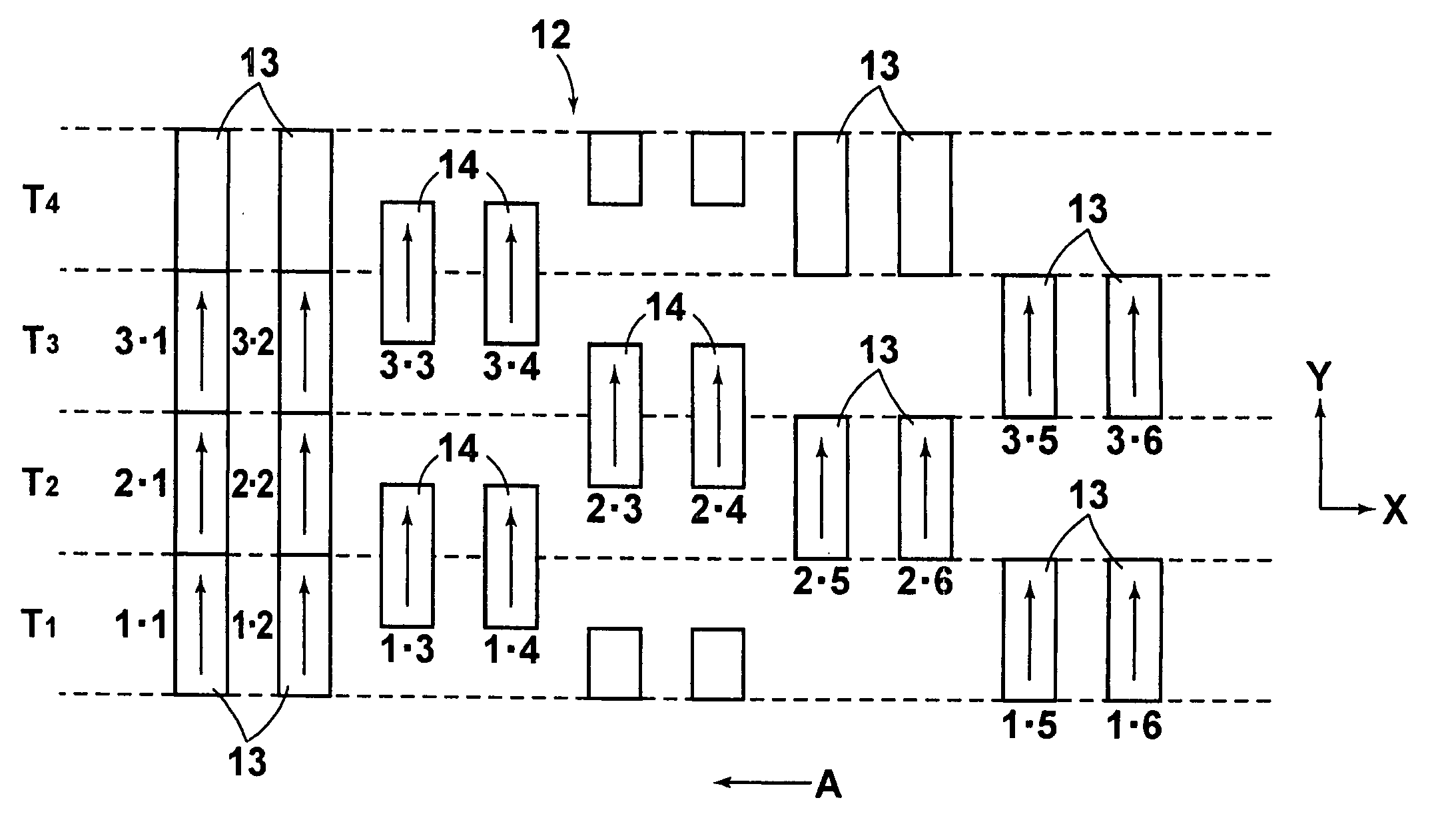
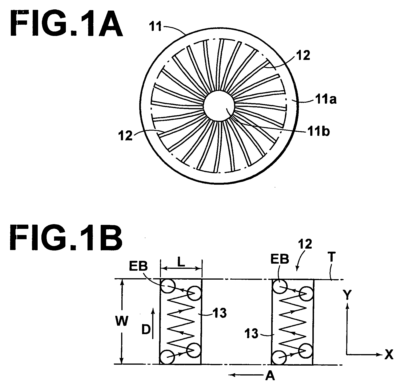
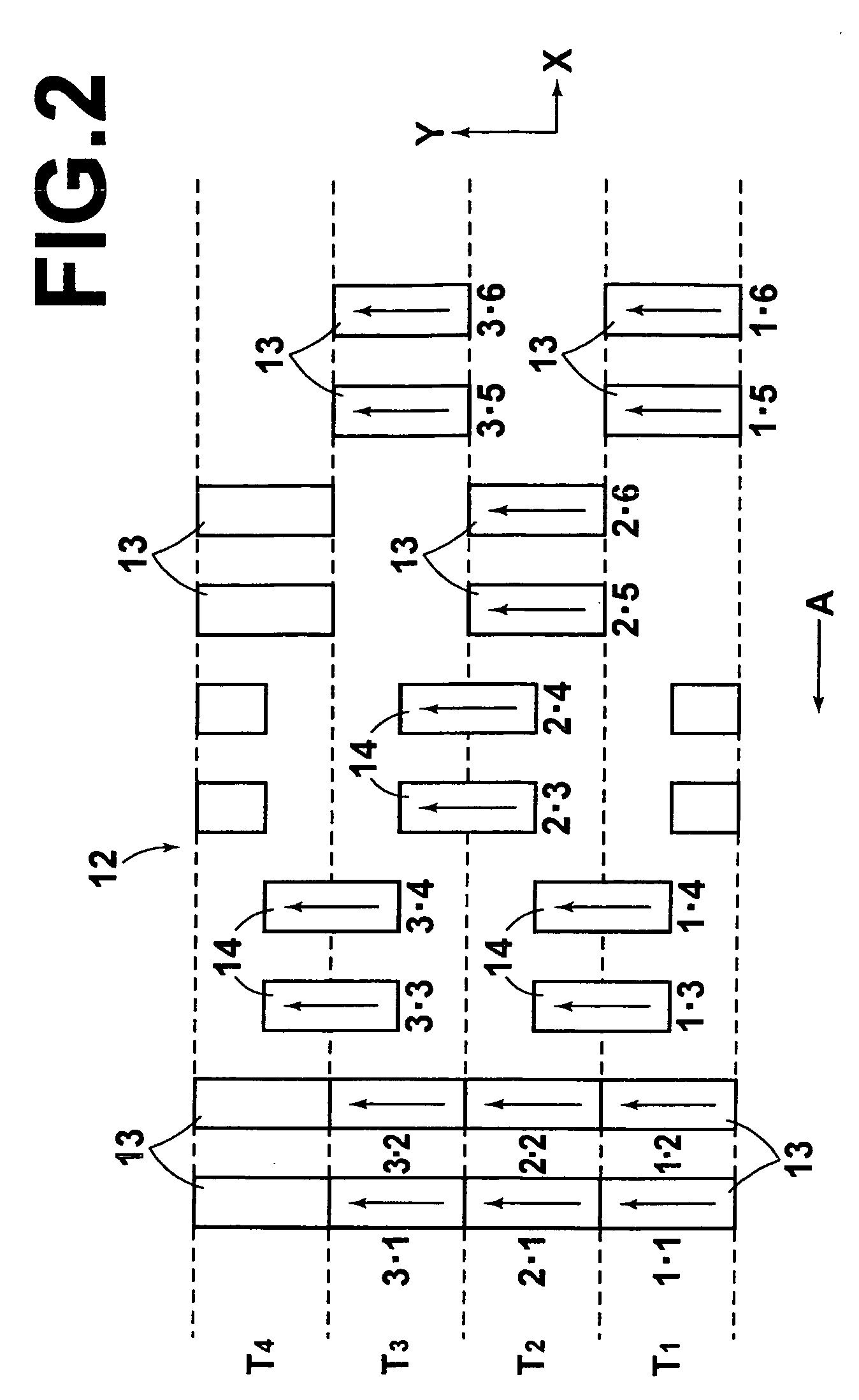
[0119] First, a first embodiment of the electron beam lithography method of the present invention will be described. FIG. 1A is a plan view of a transfer pattern to be drawn on a master carrier for magnetic transfer by the electron beam lithography method of the present invention. FIG. 1B is an enlarged schematic view of a basic lithography method for drawing elements that constitute the transfer pattern. FIG. 2 is an enlarged schematic view that illustrates a drawing order for servo patterns. FIG. 3A is a side view of the main parts of an embodiment of the electron beam lithography apparatus for executing the electron beam lithography method of the present invention. FIG. 3B is a plan view of the electron beam lithography apparatus.

[0120] As illustrated in FIG. 1A, a transfer pattern 12 (servo pattern) constituted by fine protrusions and recesses, which is...


PUM


Abstract

A fine pattern having first elements within track widths and second elements, which are shifted half a track pitch from the first elements, are drawn across the entire surface of a disk accurately and at high speed. A transfer pattern for a magnetic transfer master carrier is drawn by scanning an electron beam on a disk coated with resist. The first elements and the second elements, which are shifted half a track pitch such that they straddle adjacent tracks, are drawn. While the disk is rotated unidirectionally, the electron beam is deflected in the radial direction within a single track of the disk to draw the first elements. Deflection of the electron beam in the radial direction is shifted half a track, to draw the second elements that straddle adjacent tracks at the same time.

Description

BACKGROUND OF THE INVENTION [0001] 1. Field of the Invention [0002] The present invention relates to an electron beam lithography method, for drawing and exposing elements that constitute an uneven transfer pattern on a master carrier for magnetic transfer, by irradiating an electron beam on a resist provided on a disk. [0003] The present invention also relates to a patterned master for magnetic transfer, having a transfer pattern that corresponds to an amplitude servo pattern constituted by amplitude servo signals. [0004] Further, the present invention relates to a lithography method, for drawing and exposing elements that constitute the transfer pattern on the patterned master carrier for magnetic transfer, by irradiating an electron beam on a resist provided on a disk. [0005] Still further, the present invention relates to a preformatted magnetic recording medium. [0006] 2. Description of the Related Art [0007] Accompanying increases in amounts of data, magnetic recording media, ...

Claims


Application Information

Patent Timeline
Patent Type & Authority Applications(United States)
IPC IPC(8): G21K5/10G21G5/00
CPCB82Y10/00B82Y40/00Y10S430/143G11B5/865H01J37/3174G11B5/743
Inventor USA, TOSHIHIROKOMATSU, KAZUNORI
Owner FUJIFILM HLDG CORP
Why Eureka
Try Eureka