Antenna

a multi-frequency transmit and/or receive antenna technology, applied in the structure of radiating elements, elongated active elements, resonance antennas, etc., can solve the problems of difficult miniaturization of antennas, difficult to lower the cost, and difficult to miniaturize antennas, so as to reduce the cost, reduce the cost, and facilitate the effect of configuration

Inactive Publication Date: 2006-01-26
FDK CORP
View PDF1 Cites 78 Cited by
  • Summary
  • Abstract
  • Description
  • Claims
  • Application Information

AI Technical Summary

Benefits of technology

[0011] This invention was made in view of the above problems, an object thereof is to provide an antenna wherein an antenna element that can resonate at a plurality of frequency bands can be configured easily and at low cost with not a complex, high-cost spatial structure but a conductor pattern formed two-dimensionally along a surface of a substrate, wherein the sizes, especially length, of the conductor pattern needed in the configuration can be made smaller, and wherein in spite of the structure being suitable for being miniaturized and lowering cost, good electric characteristics are achieved for a plurality of frequency bands other than those of harmonics.

Problems solved by technology

The former theoretically has a wideband and is suitable for use as a multi-band antenna, but since having to be configured to have an equivalently infinite length, it is difficult to miniaturize the antenna.
However, there are the following problems with the above conventional antennas.
For example, those described in Japanese Patent Laid-Open Publications No. 2000-68737 and No. 2001-144524 need to have a spatial (three-dimensional) structure, and hence, it is difficult to miniaturize the antenna due to the complexity of the configuration and also to lower the cost is difficult due to lowness of suitability for manufacture, especially mass productivity.
The antenna of Japanese Patent Laid-Open Publication No. 6-232625 is relatively simple in shape, but since having a spatial structure like the above, is not suitable for lowering cost.
Furthermore, because of its configuration wherein a plurality of radiation conductors having a wide area are positioned above and Opposite each other, radiation efficiency is likely to be reduced.
It takes a large area to form a plurality of conductor patterns that form radiation conductors to resonate independently at their respective frequencies, and thus it is difficult to miniaturize the antenna .
However, although this technology is effective for antennas for relatively long wavelengths such as HF and VHF, it is not appropriate to apply to antennas for ultra high frequency ranges mainly using a distributed constant.
Even if possible, the structure will become very complex and not miniature and low in cost.

Method used


Image

  • Antenna
  • Antenna
  • Antenna

Examples


Embodiment Construction

[0029] At least the following matters will be made clear through the present specification and the description of the accompanying drawings.

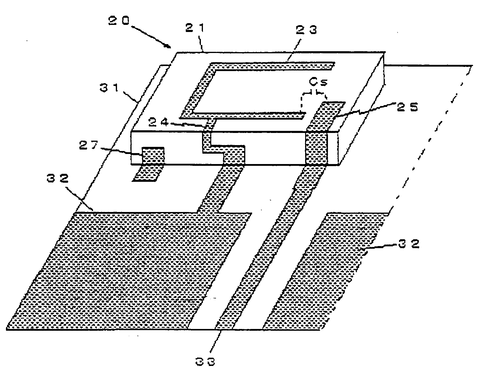
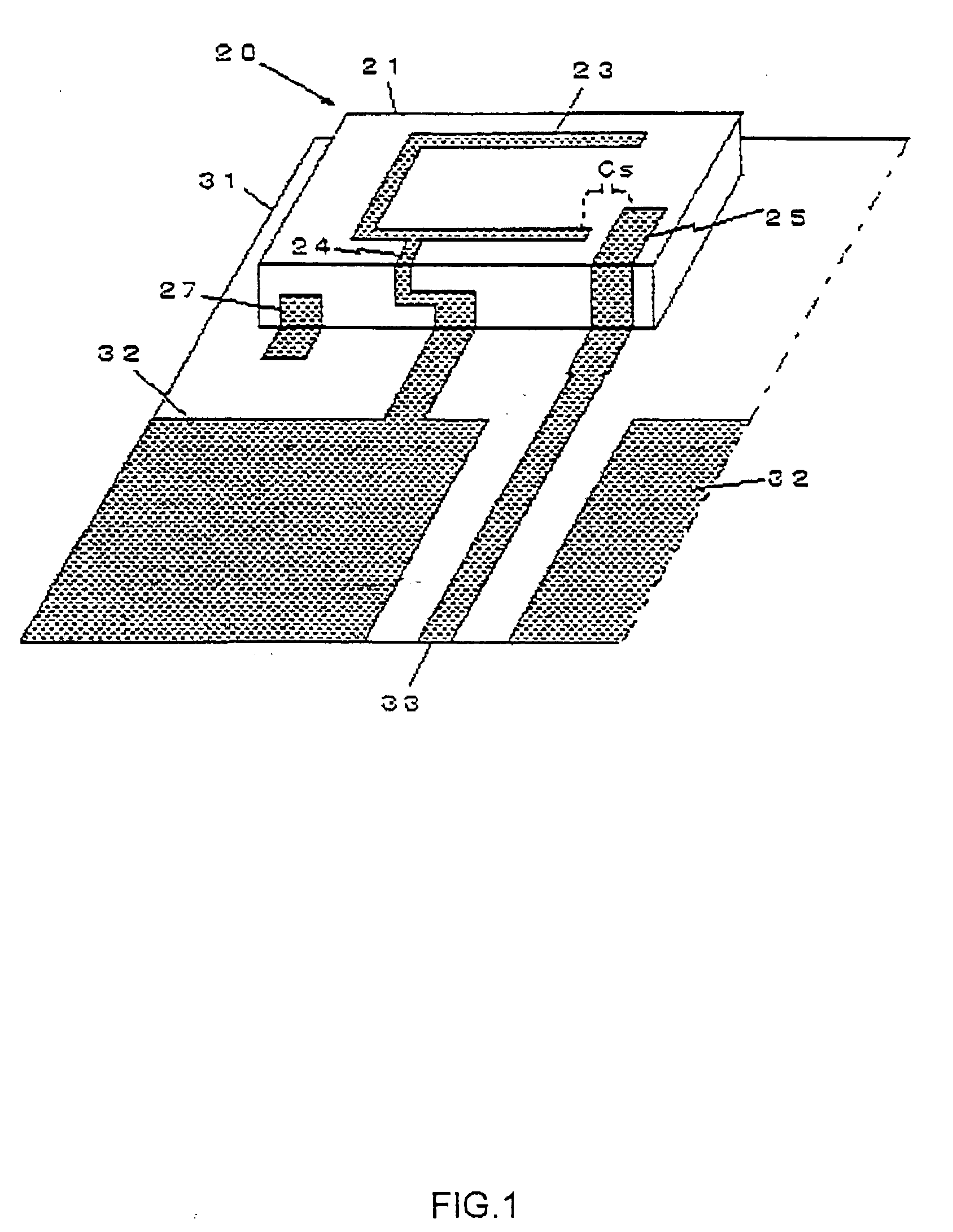
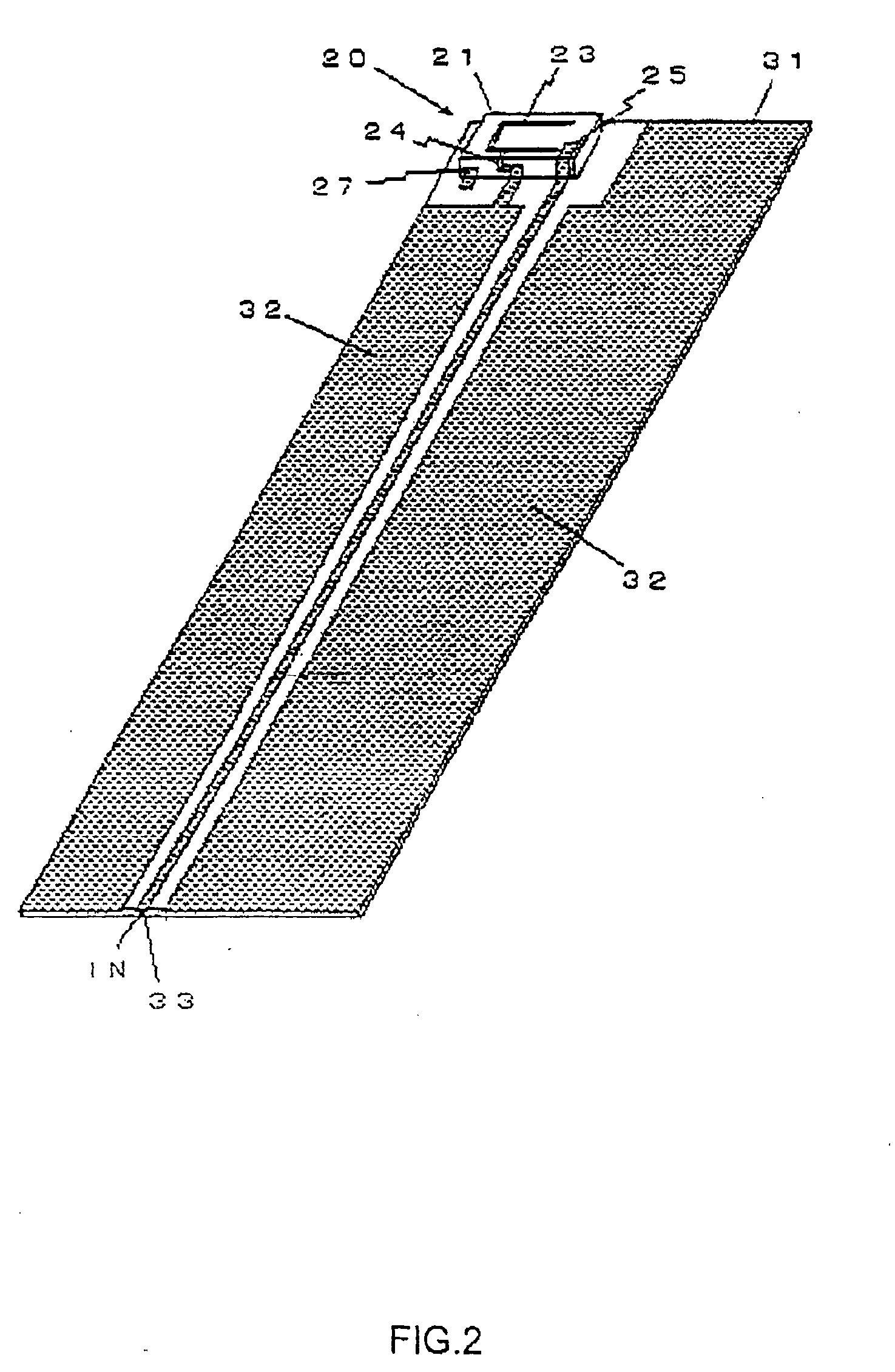
[0030] The present invention is an antenna for transmission and / or receipt having a single feeder comprising an active antenna element in which an antenna current excited by feeding is distributed in a line to radiate electromagnetic waves, said active antenna element having a conductor pattern formed two-dimensionally on surfaces of a dielectric substrate made of a dielectric of a high dielectric constant and low loss and surface-mounted as a chip component on a print circuit board, said antenna element being configured such that a plurality of distribution paths for the antenna current are formed to be different in length to each other, wherein said antenna element constitutes a grounded-type antenna in which said antenna current is copied in a ground conductor, and comprises a linear main radiation conductor, of which one end is a feeding en...


PUM


Abstract

The transmit / receive antenna has an active element with a two-dimensional conductor pattern formed on the surface of a dielectric substrate, surface-surface mounted to a PC board, and forming plural distribution paths of mutually different length. Antenna current is copied into a ground conductor such that the antenna element defines a linear main radiator, having a feeding end and an open end, forming a first distribution path, and a linear short-circuiting branching T-conductor, forming a second distribution path. A third distribution path is formed across the main radiation conductor leading to the ground conductor. This configuration produces two resonance frequency bands, exclusive of harmonics. The main radiation conductor and the feeding conductor are formed by conductor patterns on the dielectric substrate and the short-circuiting conductor is formed by a conductor pattern over the upper surface and side surface of the dielectric.

Description

CROSS-REFERENCE TO RELATED APPLICATIONS [0001] This application is a continuation of the International Application No. PCT / JP20041000244 tiled on Jan. 15, 2004 designating the United States of America. BACKGROUND OF THE INVENTION [0002] 1. Field of the Invention [0003] The present invention relates to a multi-frequency transmit and / or receive antenna having a single feeder and a plurality of resonance frequency bands, and particularly to an antenna for ultra high frequencies in or higher than a microwave range, which can be used in small radio communication apparatuses such as mobile communication apparatuses, a radio LAN (Local Area Network), an ITS (Intelligent Transport System), an ETC (Electronic Toll Collection System), and a GPS (Global Positioning System). [0004] 2. Description of the Related Art [0005] Such antennas can be classified into two main types: a traveling-wave type (non-resonance type) wherein radio signal waves are made to travel through a radiation conductor con...

Claims


Application Information

Patent Timeline
Patent Type & Authority Applications(United States)
IPC IPC(8): H01Q1/38H01Q21/30H01Q1/24H01Q5/10H01Q5/371H01Q9/04H01Q9/30H01Q9/42H01Q13/08
CPCH01Q1/243H01Q1/38H01Q5/364H01Q9/42H01Q9/0421
Inventor OKAWARA, KAZUHIKOOKABE, HIROYUKI
Owner FDK CORP
Why Eureka
Try Eureka