Antenna unit and portable radio system comprising antenna unit
- Summary
- Abstract
- Description
- Claims
- Application Information
AI Technical Summary
Benefits of technology
Problems solved by technology
Method used
Image
Examples
first embodiment
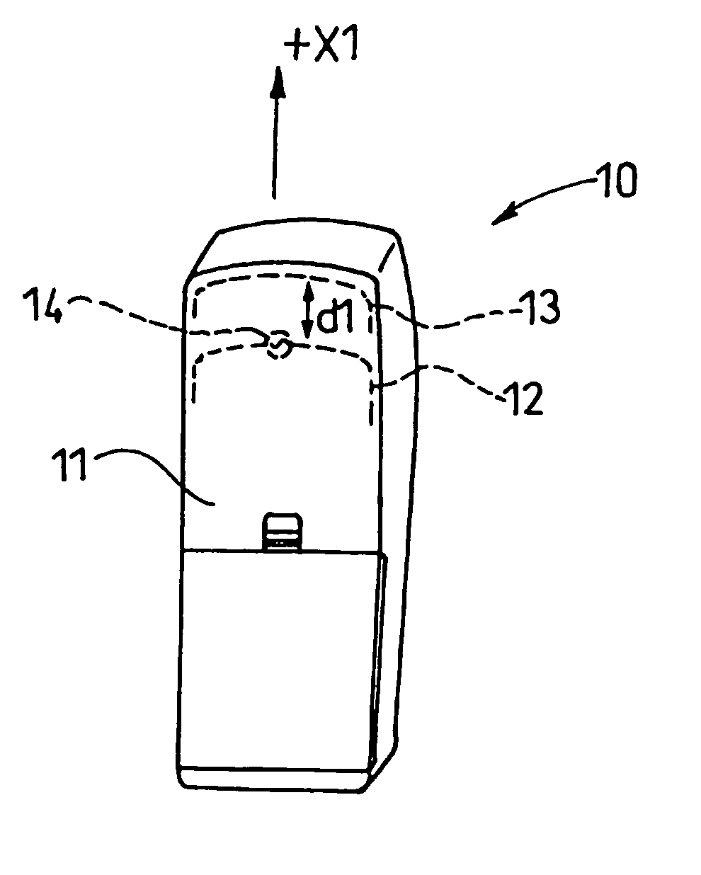
[0081]FIG. 4 is an appearance view of the back surface side of a mobile phone 10 of a W-CDMA (Wideband Code Division Multiple Access) system into which an antenna unit according to a first embodiment of the present invention is incorporated. FIG. 4 shows a perspective view when a not-shown LCD (Liquid Crystal Display) screen and a key portion are arranged to direct toward the back of this sheet. In this case, as with the transmitted / received frequencies in this W-CDMA system, the transmitting frequency is set to 1920 MHz to 1980 MHz and the receiving frequency is set to 2110 MHz to 2170 MHz.
[0082] The mobile phone 10 shown in FIG. 4 has an antenna element 12 and a parasitic element 13 in a rod-like housing 11. For example, a size of this housing 11 has a length of 110 mm in the longitudinal direction, a length of 40 mm in the width direction, and a length of 15 mm in the thickness direction. The LCD and the key portion, although not shown, are arranged on an upper portion and a low...
second embodiment
[0101]FIG. 5 is a perspective appearance view showing a mobile phone 20 corresponding to a particular communication system into which an antenna unit according to a second embodiment of the present invention is incorporated. In this case, in this embodiment, the same reference symbols are affixed to the same portions as those in the first embodiment and their duplicate explanation will be avoided herein.
[0102] The mobile phone 20 in the present embodiment has the same basic configuration as that of the mobile phone 10 shown in FIG. 4 in the first embodiment. As the communication system used herein, for example, the receiving frequency of 2300 MHz to 2350 MHz and the transmitting frequency of 2400 MHz to 2450 MHz are employed respectively and the receiving frequency is set lower than the transmitting frequency conversely to the first embodiment.
[0103] The mobile phone 20 shown in FIG. 5 has an antenna element 22 and a parasitic element 23 in the rod-like housing 11. A size of the h...
third embodiment
[0114]FIG. 6 is an appearance view of a mobile phone 30 of the W-CDMA system into which an antenna unit according to a third embodiment is incorporated. In this case, in this embodiment, the same reference symbols are affixed to the same portions as those in the first embodiment and their duplicate explanation will be avoided herein.
[0115] The mobile phone 30 shown in FIG. 6 has the same basic configuration as the mobile phone 10 in the first embodiment, and has an antenna element 32 and a parasitic element 33 in the rod-like housing 11. Also, in the mobile phone 30 in the present embodiment, a length in the longitudinal direction of the housing 11 is 110 mm, a length in the width direction is 40 mm, and a length in the thickness direction is 15 mm. As with the transmitting / receiving frequencies in this W-CDMA system, as described in the first embodiment, the transmitting frequency is 1920 MHz to 1980 MHz while the receiving frequency is 2110 MHz to 2170 MHz.
[0116] In the antenna ...
PUM
 Abstract
Description
Claims
Application Information
 - R&D
- Intellectual Property
- Life Sciences
- Materials
- Tech Scout
- Unparalleled Data Quality
- Higher Quality Content
- 60% Fewer Hallucinations
Browse by: Latest US Patents, China's latest patents, Technical Efficacy Thesaurus, Application Domain, Technology Topic, Popular Technical Reports.
© 2025 PatSnap. All rights reserved.Legal|Privacy policy|Modern Slavery Act Transparency Statement|Sitemap|About US| Contact US: help@patsnap.com


