Transceiver-integrated antenna

Active Publication Date: 2006-01-26
DENSO CORP
View PDF11 Cites 13 Cited by
  • Summary
  • Abstract
  • Description
  • Claims
  • Application Information

AI Technical Summary

Benefits of technology

[0018] In each of the above described structures, the ground plate serves as not only a plane for grounding the antenna element(s), but also a radiator for dissipating the heat emitted from the transceiver. Accordingly, with the present invention, the vehicle-installed integrated antenna

Problems solved by technology

However, conventional transceiver-integrated antennas have a problem in that their production costs are high, because they must have a heat radiating member

Method used


Image

  • Transceiver-integrated antenna
  • Transceiver-integrated antenna
  • Transceiver-integrated antenna

Examples


Example

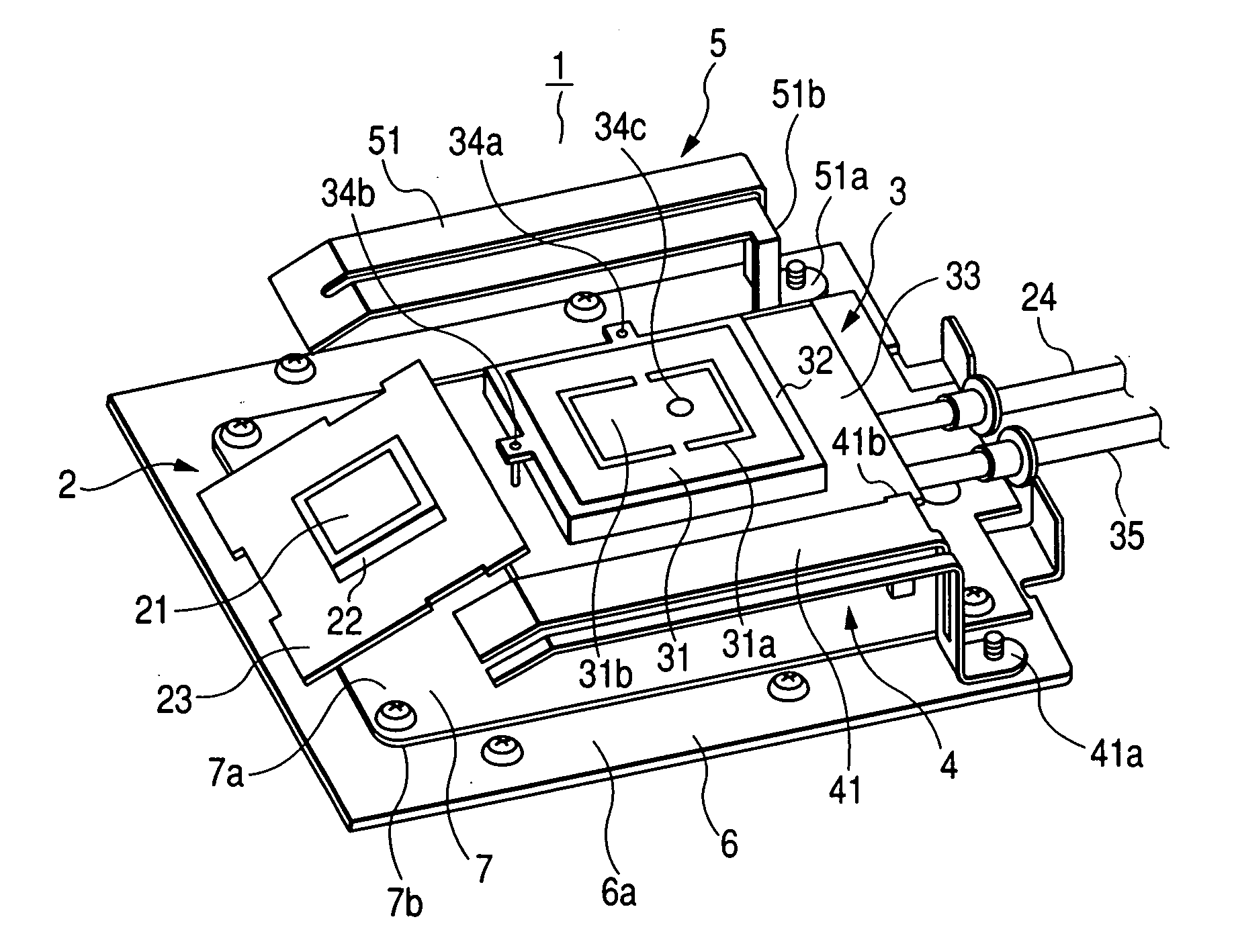
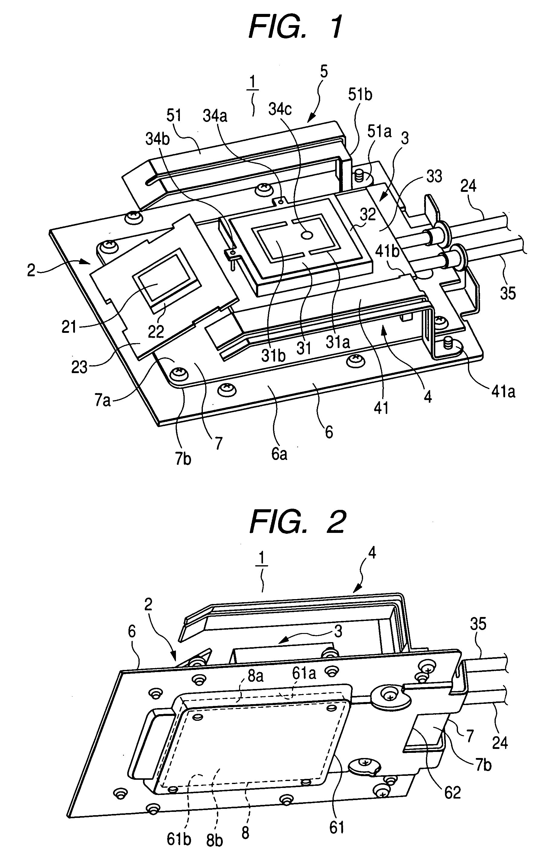
[0023]FIG. 1 is a perspective view of a vehicle-installed type transceiver-integrated antenna 1 (referred to as vehicle-installed integrated antenna 1, or integrated antenna 1 hereinafter) according to an embodiment of the invention viewed from above. This integrated antenna 1 includes an antenna element 2 for the ETC (Electronic Toll Collection system), an antenna element 3 for GPS (Global Positioning System) / VICS (Vehicle Information Communications System), and telephone antenna elements 4 and 5 for the automobile telephone system.

[0024] The ETC antenna element 2 is constituted by an ETC circuit board 23, a rectangular parallelepiped dielectric 22 mounted on the ETC circuit board 23, and a rectangular electrode 21 formed on the dielectric 22.

[0025] The ETC antenna element 2 is connected to one end of a coaxial cable 24 the other end of which is connected to an ETC connector (not shown) connectable to an ETC transceiver (not shown). The ETC antenna element 2 is installed such tha...


PUM


Abstract

The transceiver-integrated antenna includes an antenna element, a ground plate for grounding the antenna element, and a transceiver configured to transmit and receive radio signals through the antenna element. The transceiver is housed in a recess formed in the ground plate. The ground plate serves as not only a plane for grounding the antenna element, but also a radiator for dissipating the heat emitted from the transceiver.

Description

CROSS-REFERENCE TO RELATED APPLICATION [0001] This application is related to Japanese Patent Application No. 2004-212927 filed on Jul. 21, 2004, the contents of which are hereby incorporated by reference. BACKGROUND OF THE INVENTION [0002] 1. Field of the Invention [0003] The present invention relates to a transceiver-integrated antenna including an antenna element, and a transceiver which is integrated to the antenna element and configured to transmit and receive radio signals through the antenna element. [0004] 2. Description of Related Art [0005] As described, for example, in Japanese Patent Application Laid-open No. 2002-111377, it is known to use an integrated antenna including a plurality of different antenna elements used for different radio communication systems for the purpose of saving antenna installation space. It is also known to use a transceiver-integrated antenna including an antenna element and a transceiver for the purpose of saving antenna installation space, and ...

Claims


Application Information

Patent Timeline
IPC IPC(8): H01Q1/48
CPCH01Q1/3208H01Q1/38H01Q21/28H01Q9/0407H01Q9/42H01Q1/48
Inventor KOIDE, SHIROU
Owner DENSO CORP
Why Eureka
Try Eureka