Method for manufacturing electrostatic attraction type liquid discharge head, method for manufacturing nozzle plate, method for driving electrostatic attraction type liquid discharge head, electrostatic attraction type liquid discharging apparatus, and liquid discharging apparatus

a technology of electrostatic attraction and liquid discharge head, which is applied in the direction of electrostatic spraying apparatus, instruments, photomechanical treatment, etc., can solve the problems of limiting the number of droplets per minute, increasing the cost of driving control of voltage, and affecting safety, so as to improve reliability and ease of jetting control , the effect of improving the durability of the apparatus

Inactive Publication Date: 2006-01-26
NAT INST OF ADVANCED IND SCI & TECH
View PDF3 Cites 35 Cited by
  • Summary
  • Abstract
  • Description
  • Claims
  • Application Information

AI Technical Summary

Benefits of technology

[0125] By setting the upper limit of the jetting voltage in this way, it is possible to make the jetting control easier and to easily improve reliability further by further improving durability of the apparatus and by performing

Problems solved by technology

However, the above-mentioned inkjet recording method has the following problems.
Since a nozzle diameter is large, a shape of a droplet jetted from a nozzle is not stabilized, and there is a limit of making a droplet minute.
Accordingly, in order to apply a high voltage, a driving control of a voltage becomes expensive, and further, there is a problem in the aspect of safety.
In an electrostatic sucking type inkjet of a type comprising a minute nozzle or comprising a minute nozzle with an edge portion thereof protruding in the present invention, such a cleaning method generates unevenness of a cleaning property and therefore it is not preferable, and further, it is not possible to manage cleaning in the minute nozzle and cleaning a passage.
However, in regard to the type comprising a minute nozzle or comprising a minute nozzle with an edge portion thereof protruding, by only cleaning the outside surface, a cleaning unevenness is similarly generated and therefore it is not preferable, and it is not possible to deal with cleaning in the minute nozzle and cleaning the passage.
For example, when aggregates are forme

Method used


Image

  • Method for manufacturing electrostatic attraction type liquid discharge head, method for manufacturing nozzle plate, method for driving electrostatic attraction type liquid discharge head, electrostatic attraction type liquid discharging apparatus, and liquid discharging apparatus
  • Method for manufacturing electrostatic attraction type liquid discharge head, method for manufacturing nozzle plate, method for driving electrostatic attraction type liquid discharge head, electrostatic attraction type liquid discharging apparatus, and liquid discharging apparatus
  • Method for manufacturing electrostatic attraction type liquid discharge head, method for manufacturing nozzle plate, method for driving electrostatic attraction type liquid discharge head, electrostatic attraction type liquid discharging apparatus, and liquid discharging apparatus

Examples


first embodiment

[0216] A first embodiment will be described with reference to FIG. 11 to FIG. 21.

[0217] An electrostatic sucking type droplet jetting apparatus as an embodiment to which the present invention is applied, as shown in FIG. 11, comprises an electrostatic sucking type liquid jetting head 100 having first liquid room barriers 106, 106, . . . and second liquid room barriers 107, 107, . . . , as a convex meniscus forming section; a supplying pump for giving a supplying pressure of the liquid solution to each liquid solution supplying channel 101 of the liquid jetting head 100; and a circuit (jetting voltage applying section 25 and counter electrode 23 shown in FIG. 13 and FIG. 14) for driving the liquid jetting head 100.

[0218] The liquid jetting head 100 will be described by using FIG. 11. Here, FIG. 11 is a perspective view showing a bottom surface of the liquid jetting head 100 as the embodiment to which the present invention is applied, with the bottom surface located at the front sid...

second embodiment

[0275] A second embodiment to which the present invention is applied will be described with reference to FIG. 23 to FIG. 28.

[Whole Structure of Liquid Jetting Apparatus]

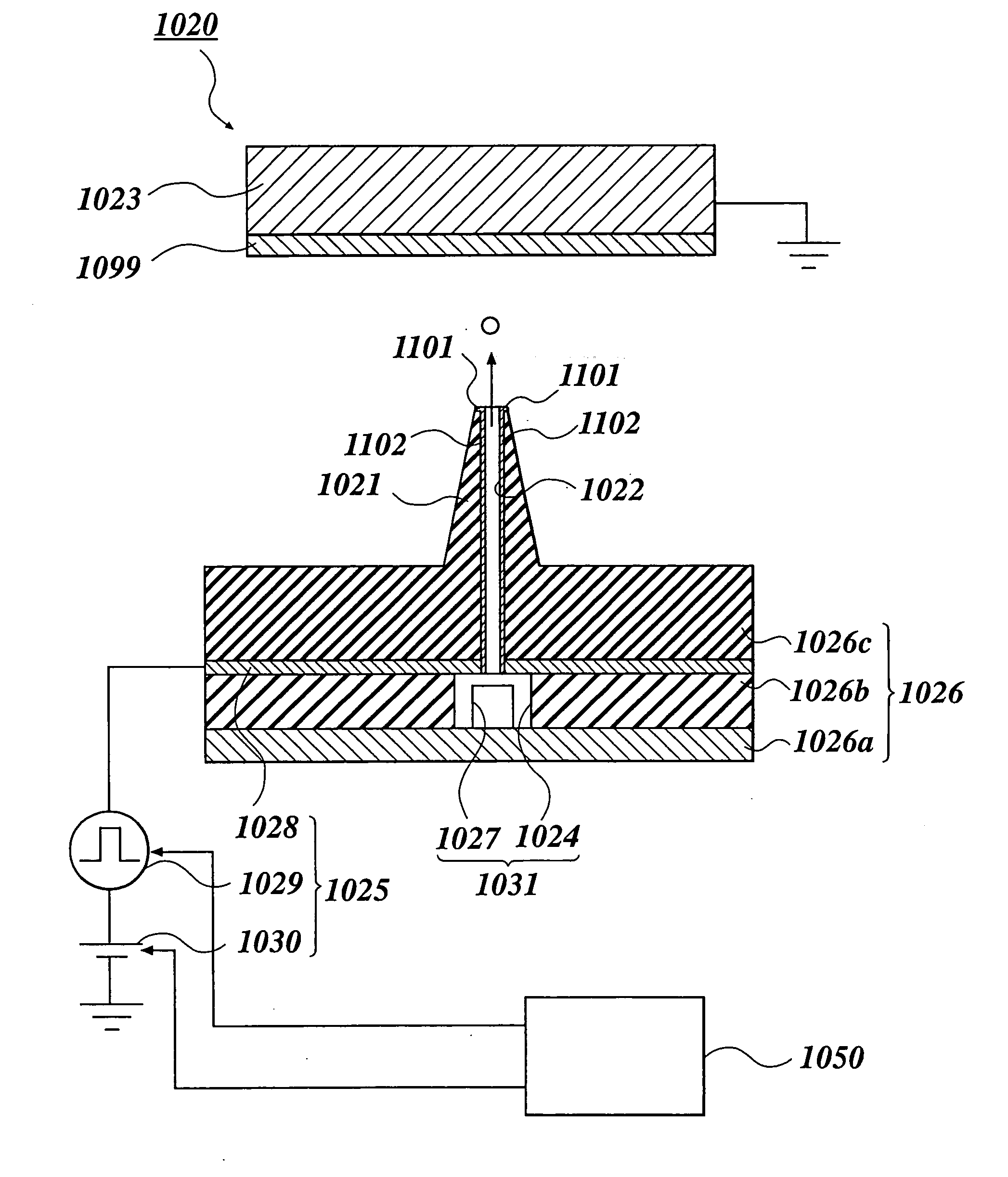
[0276]FIG. 23 is a view showing a whole structure of a liquid jetting apparatus 1020 in the second embodiment to which the liquid jetting apparatus of the present invention is applied. In FIG. 23, the apparatus is shown with a part thereof cut out along a nozzle 1021. First, the whole structure of the liquid jetting apparatus 1020 will be described with reference to FIG. 23.

[0277] This liquid jetting apparatus 1020 comprises the nozzle 1021 having a super minute diameter for jetting a droplet of chargeable liquid solution from its edge portion; a counter electrode 1023 having a facing surface facing the edge portion of the nozzle 1021 and supporting a base member 1099 for receiving the landing of the droplet; a liquid solution supplying section 1031 for supplying the liquid solution to a passage 1022 in the nozzle...

third embodiment

[0319] A third embodiment to which the present invention is applied will be described with reference to FIG. 29, FIG. 30A, FIG. 30B and FIG. 30C.

[0320]FIG. 29 is a view showing a whole structure of a liquid jetting apparatus 1040 in the third embodiment to which the liquid jetting apparatus of the present invention is applied. In FIG. 29, a part of the liquid jetting apparatus 1040 is cut out along the nozzle 1021 to be shown. FIG. 30A is a view showing a state where liquid solution in an in-nozzle passage forms meniscus in a reentrant shape at an edge portion of the nozzle 1021. FIG. 30B is a view showing a state where the liquid solution in the in-nozzle passage 1022 forms meniscus in a convex shape at the edge portion of the nozzle 1021. FIG. 30C is a view showing a state where a liquid level of the liquid solution in the in-nozzle passage 1022 is drawn into as much as a predetermined distance. As shown in FIG. 29, FIG. 30A, FIG. 30B and FIG. 30C, in the liquid jetting apparatus...


PUM


Abstract

First, through a coating step, a photolithography step and an etching step, a plurality of electrodes 142, 142, . . . are formed on a base plate 141. Next, a resist layer 143b is formed on the base plate 141 so as to cover all of the electrodes 142, 142, . . . , and by exposing and developing the resist layer 143b, a nozzle 103 having a super minute diameter is formed to stand with respect to the base plate 141 so as to make the resist layer 143b correspond to each electrode 142, and an in-nozzle passage is formed in each nozzle 103.

Description

FIELD OF THE INVENTION [0001] The present invention relates to a nozzle plate producing method for producing a nozzle plate for jetting a droplet to a base member, a producing method of an electrostatic sucking type liquid jetting head comprising the nozzle plate, an electrostatic sucking type liquid jetting head driving method for driving the electrostatic sucking type liquid jetting head, an electrostatic sucking type liquid jetting apparatus comprising the electrostatic sucking type liquid jetting head, and a liquid jetting apparatus for jetting liquid to a base member. BACKGROUND ART [0002] As a conventional inkjet recording method, a piezo method for jetting an ink droplet by changing a shape of an ink passage according to a vibration of a piezoelectric element, a thermal method for making a heat generator provided in an ink passage heat to generate air bubbles and jetting an ink droplet according to a pressure change by the air bubbles in the ink passage, and an electrostatic ...

Claims


Application Information

Patent Timeline
IPC IPC(8): B41J2/06B05B5/025B05B17/06B41J2/14B41J2/16
CPCB05B5/0255B05B17/0607B41J2/04576B41J2/04588B41J2/06B41J2/14209B41J2002/14395B41J2/16B41J2/162B41J2/1623B41J2/1631B41J2/1642B41J2/1643B41J2/1433
Inventor NISHI, YASUOHIGUCHI, KAORUMURATA, KAZUHIROYOKOYAMA, HIROSHI
Owner NAT INST OF ADVANCED IND SCI & TECH
Why Eureka
Try Eureka