Segmented electrodes for poling of ferroelectric crystal materials

Active Publication Date: 2006-01-26
ADVR
View PDF30 Cites 7 Cited by
  • Summary
  • Abstract
  • Description
  • Claims
  • Application Information

AI Technical Summary

Benefits of technology

[0008] Advantageously, at least some embodiments of the present invention achieve improved fidelity of

Problems solved by technology

Unfortunately, the pattern resulting in the poled area does not always correspond sufficiently well or predictably to the electrode shape.
Small scale pattern fidelity can be compromised, for example, due to variations in the ferroelectric crystal or crystal-to-electrode contact when domain reversed regions are cr

Method used


Image

  • Segmented electrodes for poling of ferroelectric crystal materials
  • Segmented electrodes for poling of ferroelectric crystal materials
  • Segmented electrodes for poling of ferroelectric crystal materials

Examples


Example

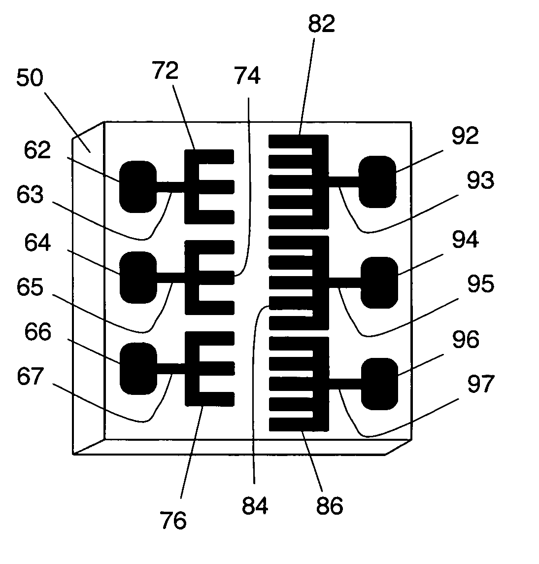
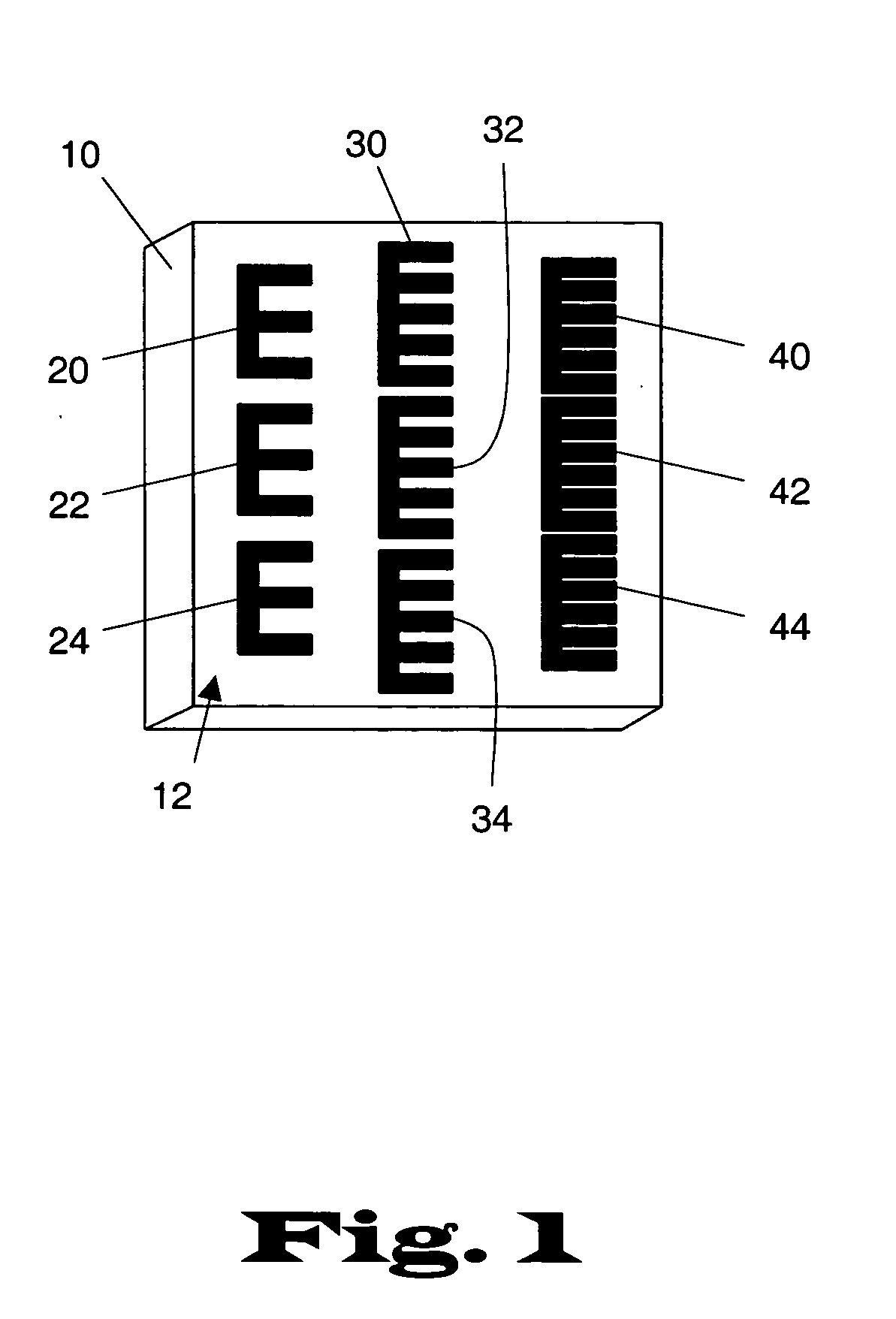
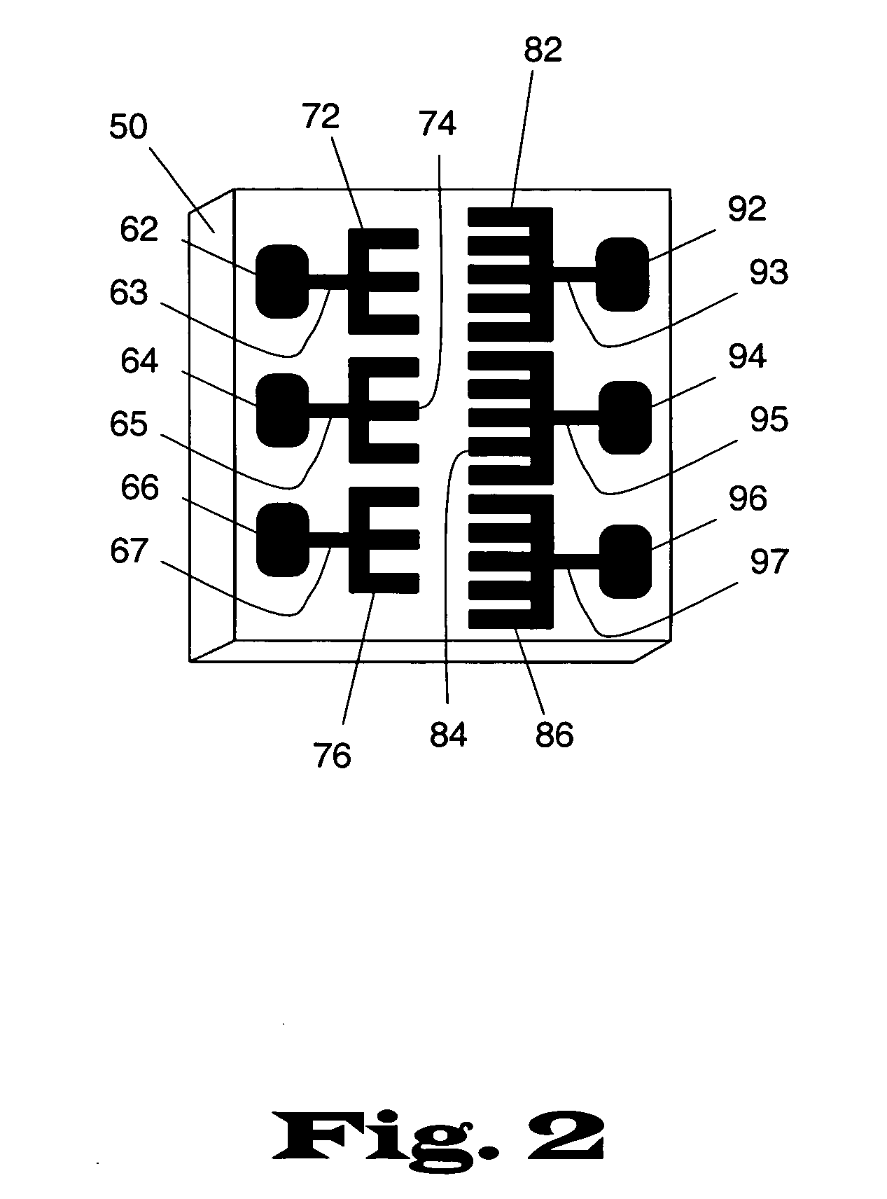
[0026] The manufacture of optical devices by deliberately aligning domains in specific patterns in ferroelectric crystal material is practiced using a segmented electrode rather than a continuous electrode on at least one of the surfaces of the ferroelectric crystal. A region that is optically effective in some manner, such as a refracting, diffracting or reflecting interface, or an interface at which the nonlinear coefficient changes sign, is created at the interface between domains of one alignment and domains of a different alignment. Independent poling voltage profiles are selectively applied to the segments using any suitable type of poling voltage system, including multiple poling voltage circuits as well as an adjustable poling voltage circuit having multiple addressable outputs. The poling voltages are used to create various electric fields inside the ferroelectric crystal so that portions of the desired domain-reversed pattern are individually established in the ferroelectr...


PUM


Abstract

The manufacture of optical devices by reversing domains in specific patterns in ferroelectric crystal material is practiced using a segmented electrode rather than a continuous electrode on at least one of the surfaces of the ferroelectric crystal material. Independent poling voltages are selectively applied to the segments to create various electric fields inside the ferroelectric crystal material. In this manner, portions of the desired domain-reversed pattern are individually established in the ferroelectric crystal material in high fidelity with their respective electrode segments so that upon completion of poling, the entire domain-reversed structure is established in the ferroelectric crystal material in high fidelity relative to the entire electrode. Parameters of the electrode segment that may be varied singly or in combination to achieve a desired degree of fidelity include the overall size of the electrode segment, as well as the shape and size of the features included in the electrode segment.

Description

BACKGROUND OF THE INVENTION [0001] 1. Field of the Invention [0002] The present invention is directed to optical devices, and more particularly to poling of ferroelectric crystal materials to create optical devices. [0003] 2. Description of the Related Art [0004] The process of reversing domains in specific patterns in a ferroelectric crystal is used to create many useful optical devices. Domain reversal, or poling, is typically accomplished by placing electrodes on the top and bottom surface of the ferroelectric crystal, then applying a voltage profile to the electrodes. One surface typically supports a single large continuous electrode, while the other surface may support a correspondingly continuous electrode or a ground plane. The applied voltage creates an electric field inside the ferroelectric crystal, and the domains become aligned with the electric field in the regions corresponding more or less to the shape of the electrode. After the applied voltage is discontinued, the d...

Claims


Application Information

Patent Timeline
IPC IPC(8): G02B6/26
CPCG02F1/3558
Inventor ROBERTS, ANTHONY D.BATTLE, PHILIP R.
Owner ADVR
Why Eureka
Try Eureka