High velocity and high dilution exhaust system

a high-dilution, exhaust system technology, applied in the direction of combustion regulation, combustion process, lighting and heating apparatus, etc., can solve the problems of contaminated exhaust being heavier than air, corrosive or foul odor, industrial and institutional processes often produce fumes that need to be exhausted, etc., to achieve the effect of removing costly corrosion

Active Publication Date: 2006-01-26
KUPFERBERG MINEL +1
View PDF8 Cites 45 Cited by
  • Summary
  • Abstract
  • Description
  • Claims
  • Application Information

AI Technical Summary

Benefits of technology

[0009] It is another object of the invention to provide an exhaust fan allowing dispersement at a height preventing exhaust from reentering a building through an air conditioning system or other roof mounted equipment.
[0010] It is still another object of the invention to allow dispersement of exhaust eliminating costly corrosion caused by exhaust vapors.

Problems solved by technology

Industrial and institutional processes often produce fumes required to be exhausted and removed from the immediate area of the building.
Improperly designed exhaust systems that ineffectively discharge high concentrations of effluent can result in entrainment of the hazardous or noxious exhaust into the building air conditioning system, contaminating the fresh air brought into the building.
Problems are encountered in particular where the contaminated exhaust is heavier than air, is corrosive or has a foul odor.
Often, the stacks are so long as to be unstable and require the use of guy wires or other braces to ensure their stability, especially if high wind conditions are ever expected.

Method used


Image

  • High velocity and high dilution exhaust system
  • High velocity and high dilution exhaust system
  • High velocity and high dilution exhaust system

Examples


Embodiment Construction

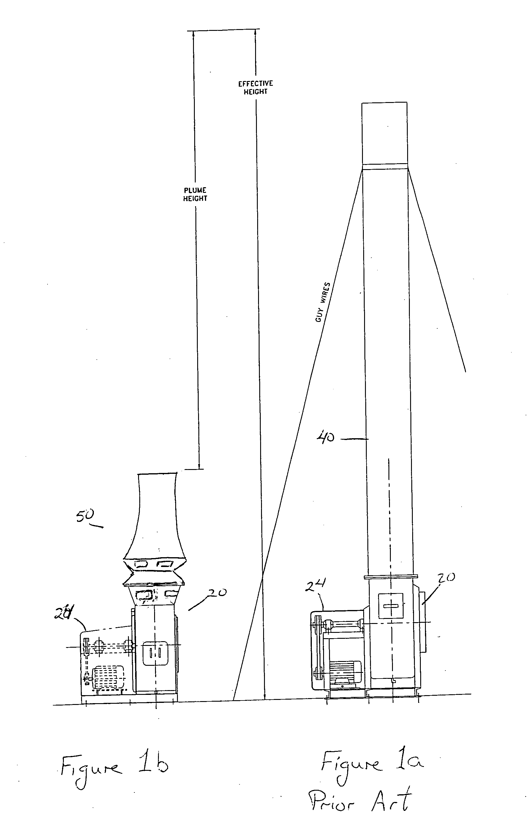
[0038]FIG. 1a shows a conventional exhaust system, as may be mounted on a roof. The centrifugal fan 20, powered by motor 24, receives exhaust from the ventilation system of the building and sends exhaust through exhaust stack 40. Upon exiting the top of the exhaust stack 40, the exhaust travels a short distance before dissipating within the ambient air. The total distance of the stack and distance traveled before dispersement is shown as the effective height.

[0039]FIG. 1b shows a centrifugal fan having the exhaust stack of the invention. The exhaust leaves the stack 50 with high velocity and stream integrity and has a plume height giving an effective height equal to that of prior art devices having a high stack. The invention has the advantage of diluting the effluent with a compact configuration.

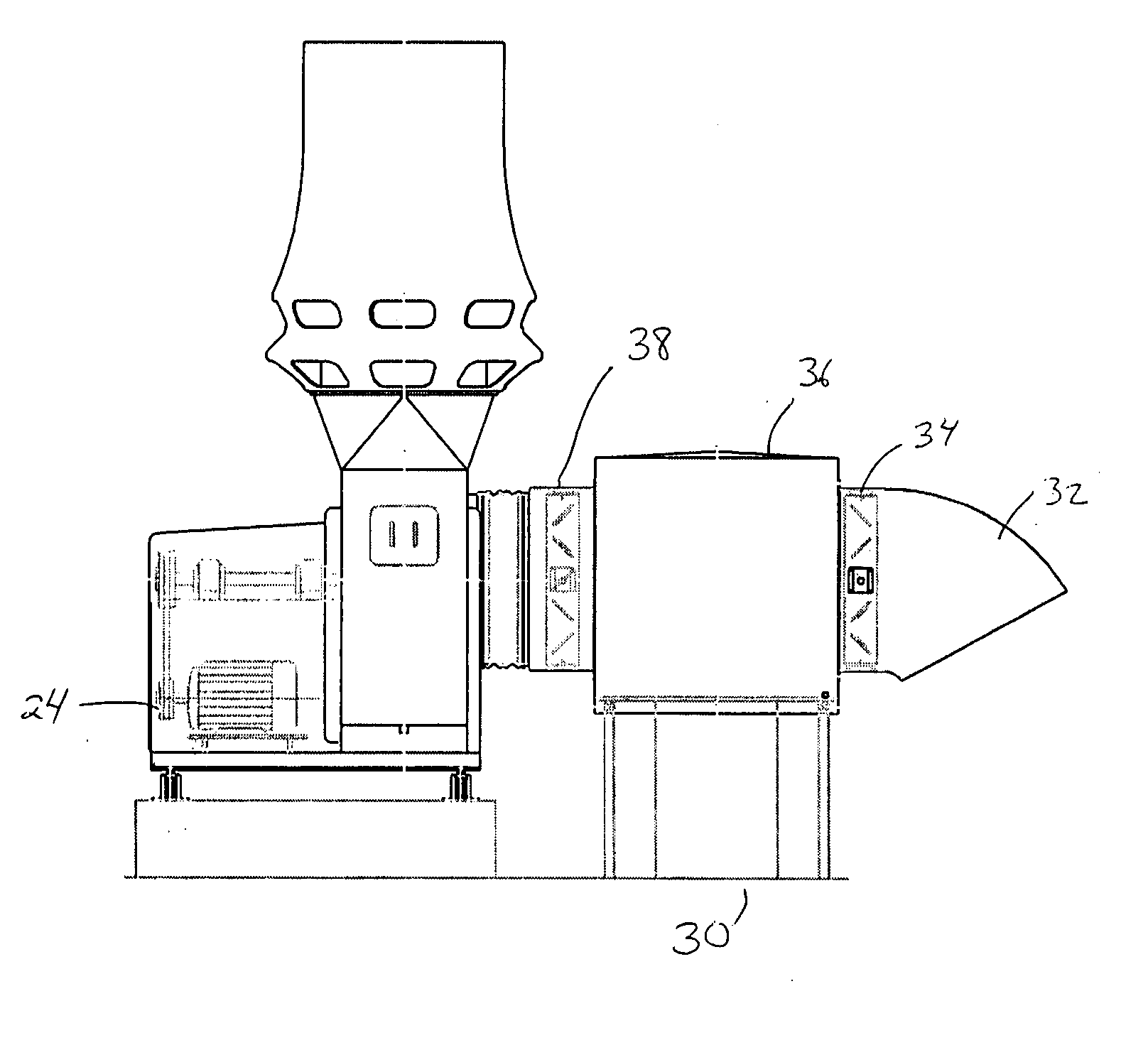
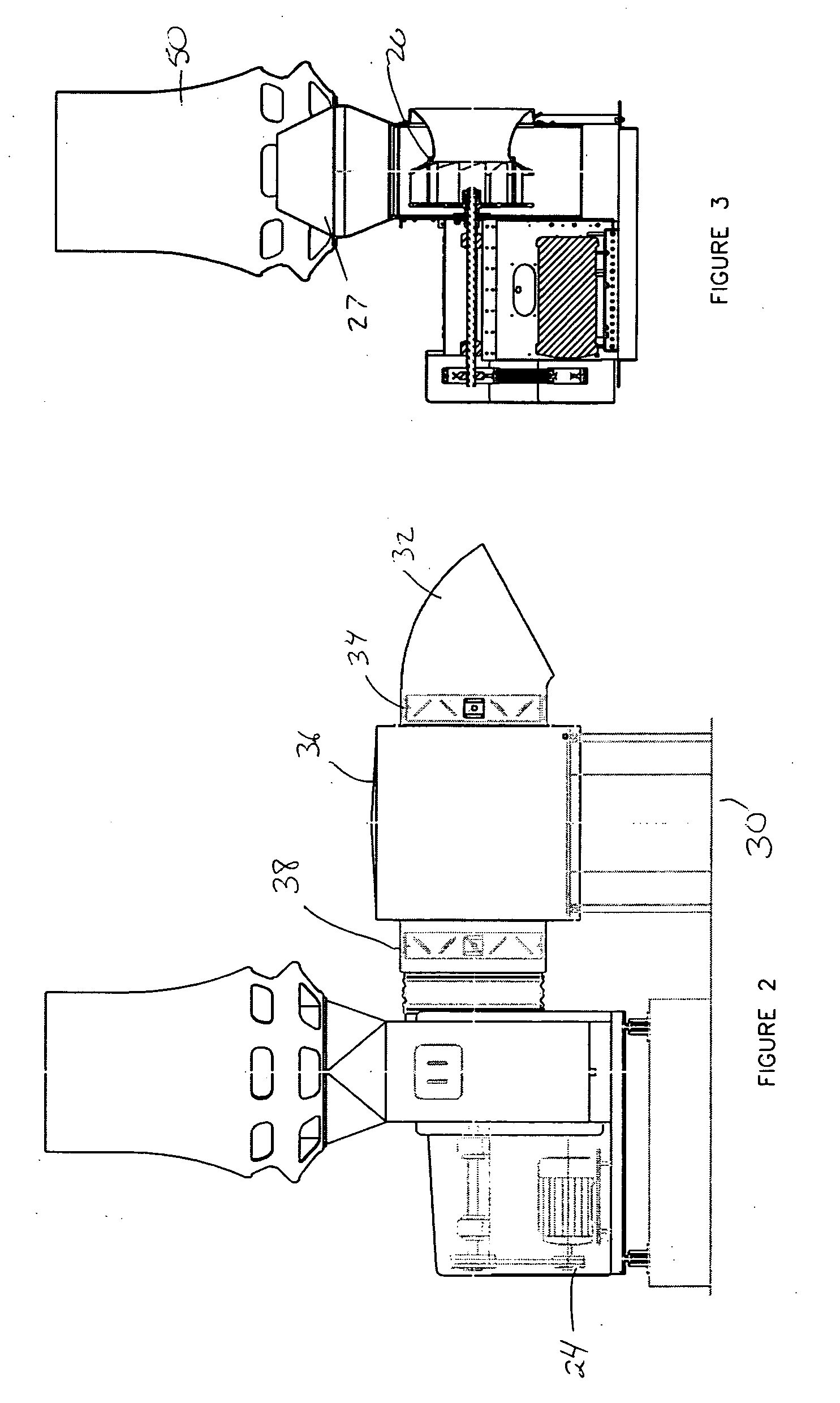
[0040]FIG. 2 shows the centrifugal fan and exhaust stack as part of a ventilation system. Exhaust is received through a duct 30 terminating at the inlet plenum 36. The inlet plenum 36 is ...


PUM


Abstract

The high velocity and high dilution exhaust system uses a centrifugal fan provided with a tapered nozzle. The nozzle compresses the airstream exiting the fan to increase back pressure and velocity. The air flow from the fan enters a stack having a venturi further increasing the velocity and decreasing the pressure. The decrease in pressure causes a suction, allowing the introduction of ambient air to mix with and dilute the output of the fan. The total discharge from the exhaust stack has a high velocity resulting in a plume height. and effective height of the exhaust before dispersion occurs.

Description

BACKGROUND OF THE INVENTION [0001] Industrial and institutional processes often produce fumes required to be exhausted and removed from the immediate area of the building. Exhaust systems include ducts, hoods, and exhaust fans to extract the contaminated fumes. Specific applications, such as laboratory or processing exhaust, are hazardous and must be exhausted to insure the safety of those working in close proximity to the source of the exhausted effluent. Safety concerns extend not only to those in the immediate area where the fumes are generated, but also to others located in the building as well as occupants in surrounding buildings. [0002] Improperly designed exhaust systems that ineffectively discharge high concentrations of effluent can result in entrainment of the hazardous or noxious exhaust into the building air conditioning system, contaminating the fresh air brought into the building. [0003] Problems are encountered in particular where the contaminated exhaust is heavier ...

Claims


Application Information

Patent Timeline
Patent Type & Authority Applications(United States)
IPC IPC(8): F23L17/02
CPCF23L17/005
Inventor KUPFERBERG, MINELROBITAILLE, MARC
Owner KUPFERBERG MINEL
Why Eureka
Try Eureka