
Wireless keying for a continuous wave (CW) amateur radio transmitter

a continuous wave (cw) and transmitter technology, applied in the direction of electrical equipment, special services for subscribers, dot-and-dash transmission equipment, etc., can solve the problems of difficult and cumbersome task of moving the telegraph sending instrument from one transceiver to another, difficult to see behind, difficult to move, etc., to achieve the effect of not easy to move, easy to see, and great possibility of electrical shock to the operator

Inactive Publication Date: 2006-01-26
DITMER LARRY R
View PDF4 Cites 41 Cited by
  • Summary
  • Abstract
  • Description
  • Claims
  • Application Information

AI Technical Summary

Benefits of technology

[0025] The objectives of the Wireless Keying System for a Continuous Wave (CW) Amateur Radio Transmitter are: to provide a Dit / Dah Decoding unit that has selectable output switching to one of a plurality of outputs, moving the connection to subsequent transceivers; to provide a non-physical connection of the sending unit to the transceiver and / or transmitter through the use of an infrared signal in place of wires, making the bench less cluttered and allowing sending unit storage off the bench when not in use; isolating the operator from electrical shock from a grounding or power problem; to provide a system that allows for rapid switching that eliminates the need for multiple sending units and the differences in feel and touch between multiple sending units; to provide an encoding unit that accepts input from all standard telegraph key systems; and to provide an encoding unit that accepts a signal directly from a computer's serial COM port eliminating the need for an external CW interface. BRIEF SUMMARY OF INVENTION

Problems solved by technology

Moving the telegraph sending instrument from one transceiver to another is a difficult and cumbersome task due to the number of wires and cables attached to the back of the transceiver.
The transceiver is not easily moved and is hard to see behind in the typical bench or shelf set-up.
The workspace in front of the transceiver is also crowded due to the various modes operation used by the amateur radio operator.
Since the sending unit is electrically connected to the transceiver and the antenna, the possibility of electrical shock to the operator is great in the event of a power and / or grounding problem.
When multiple transceivers are in use, as in a single operator contesting mode where time is of the essence, the use of a dedicated key for each transmitter is the costly and often less than satisfactory solution as each key has its own feel and touch and can slow the operator or generate errors in transmission.

Method used


Image

  • Wireless keying for a continuous wave (CW) amateur radio transmitter
  • Wireless keying for a continuous wave (CW) amateur radio transmitter
  • Wireless keying for a continuous wave (CW) amateur radio transmitter

Examples


Embodiment Construction

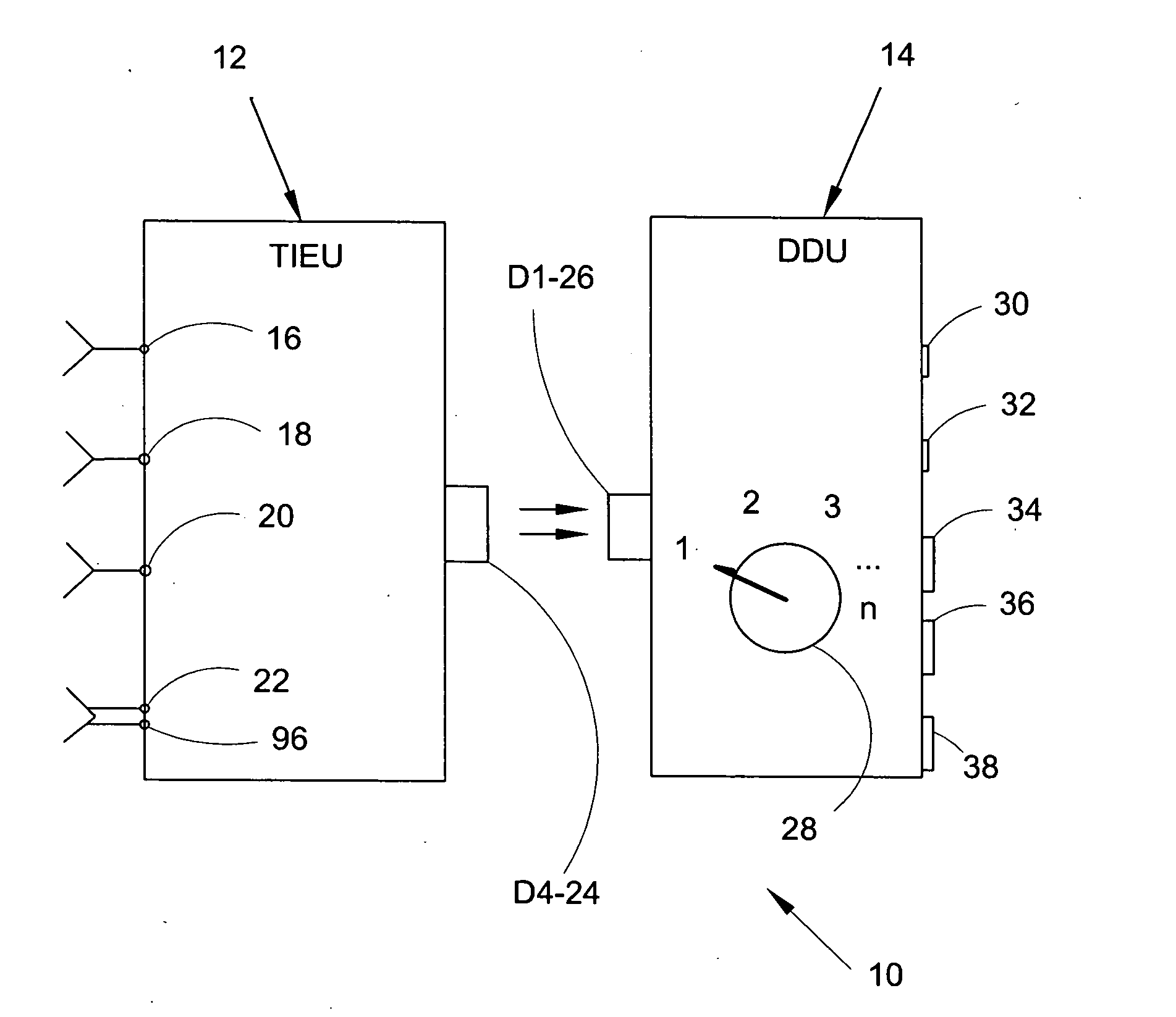
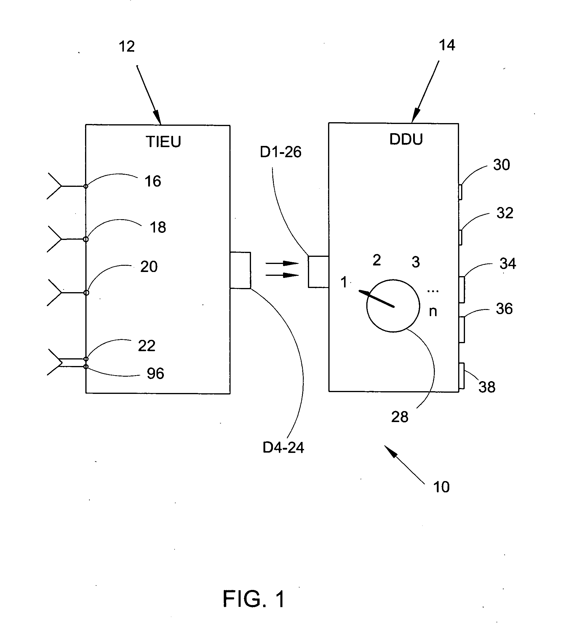
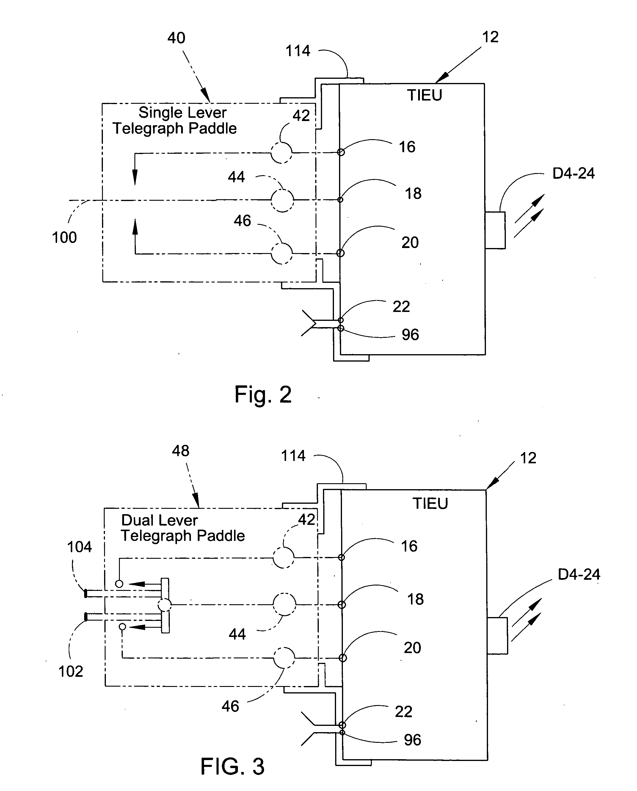
[0105] In order that the invention may be more fully understood, it will now be described by way of example with reference to the accompanying drawings which represent and illustrate several embodiments of Wireless Keying System for a continuous wave (CW) amateur radio transmitter 10. Wireless Keying System 10 can be utilized with input from personal computer 54, Telegraph hand or straight key 50, single lever telegraph paddle 40, or dual lever telegraph paddle 48 and its output is easily switched to one of several transmitters 58 through 64 by turning keyed output / transmitter selector 28 to the desired transmitter number.

[0106] Turning to FIG. 1, the two units that make up Wireless Keying System 10, Telegraph Instrument Encoding Unit (TIEU) 12 and Dit / Dah Decoding Unit (DDU) 14, are represented in block diagrams.

[0107] TIEU 12 is shown with the four possible inputs from the various sending units mentioned above. The inputs that can be received are Dah input 16, Dit / Dah reference ...


PUM


Abstract

This invention generally relates to Morse code sending keys systems. More specifically, this invention relates to a wireless key system that can select a particular amateur radio transmitter on a crowded radio bench and direct it to send Morse code messages in a continuous wave (CW) transmission mode without a physical wired connection between the wireless key and said radio transmitter. The wireless keying system is comprised of a Telegraph Instrument Encoding Unit (TIEU) and a Dit / Dah Decoding Unit (DDU). The TIEU electrically encodes the telegraph contact closures and emits an electro-optical signal, mimicking the closures made by the telegraph key. The DDU detects the emitted electro-optical signal and generates electrical signals for keying on and off the amateur radio transmitter chosen. This wireless keying system supports the transfer of Morse code signals from a telegraph hand key, a paddle key, and those generated by a computer.

Description

BACKGROUND [0001] 1. Field of Invention [0002] This invention generally relates to Morse code sending key systems. More specifically, this invention relates to a wireless key system that can select a particular amateur radio transmitter on a crowded radio bench and direct it to send Morse code messages in a continuous wave (CW) transmission mode without a physical wired connection between the wireless key and radio transmitter. [0003] 2. Prior Art [0004] U.S. Pat. No. 5,365,230 to Kikinis discloses a self-contained computer keyboard that communicates keystroke data wirelessly to its host computer via scan codes in a variable magnetic field. This is an inductively coupled system. [0005] U.S. Pat. No. 5,525,981 to Abernathy shows a cordless transducer / cursor having a transmitter for use in conjunction with the receiver of a digitizer tablet. The transmitter receives parallel binary signals representing the status of non-positional functions and the pressure applied to a stylus and con...

Claims


Application Information

Patent Timeline
Patent Type & Authority Applications(United States)
IPC IPC(8): H04M3/42
CPCH04L15/04
Inventor DITMER, LARRY R.
Owner DITMER LARRY R
Learn More