OCT laryngoscope

a laryngoscope and octave technology, applied in the field of laryngoscopes, can solve the problems of inability to reliably diagnose or diagnose pathological changes deep in the tissue structure and many pathological changes of the vocal folds cannot be reliably diagnosed, or diagnosed at all, so as to improve the diagnosis of pathological changes

Inactive Publication Date: 2006-01-26
ROWIAK GMBH
View PDF9 Cites 146 Cited by
  • Summary
  • Abstract
  • Description
  • Claims
  • Application Information

AI Technical Summary

Benefits of technology

[0006] The object of the present invention is to provide a laryngoscope for improved diagnosis of pathological changes, in particular pathological changes of the vocal folds.
[0010] The laryngoscope developed in this manner enables deeper tissue layers in the vocal folds to be imaged in a form that is very helpful for diagnosis, and therefore can also show pathological changes in these deeper tissue layers.

Problems solved by technology

However, many pathological changes of the vocal folds cannot be reliably diagnosed, or diagnosed at all, using the static observation of the vocal folds enabled by such laryngoscopes.
However, even when using this diagnostic method, it is often the case that pathological changes deep in the tissue structure of the vocal folds cannot be diagnosed or diagnosed reliably.

Method used


Image

  • OCT laryngoscope
  • OCT laryngoscope

Examples


Embodiment Construction

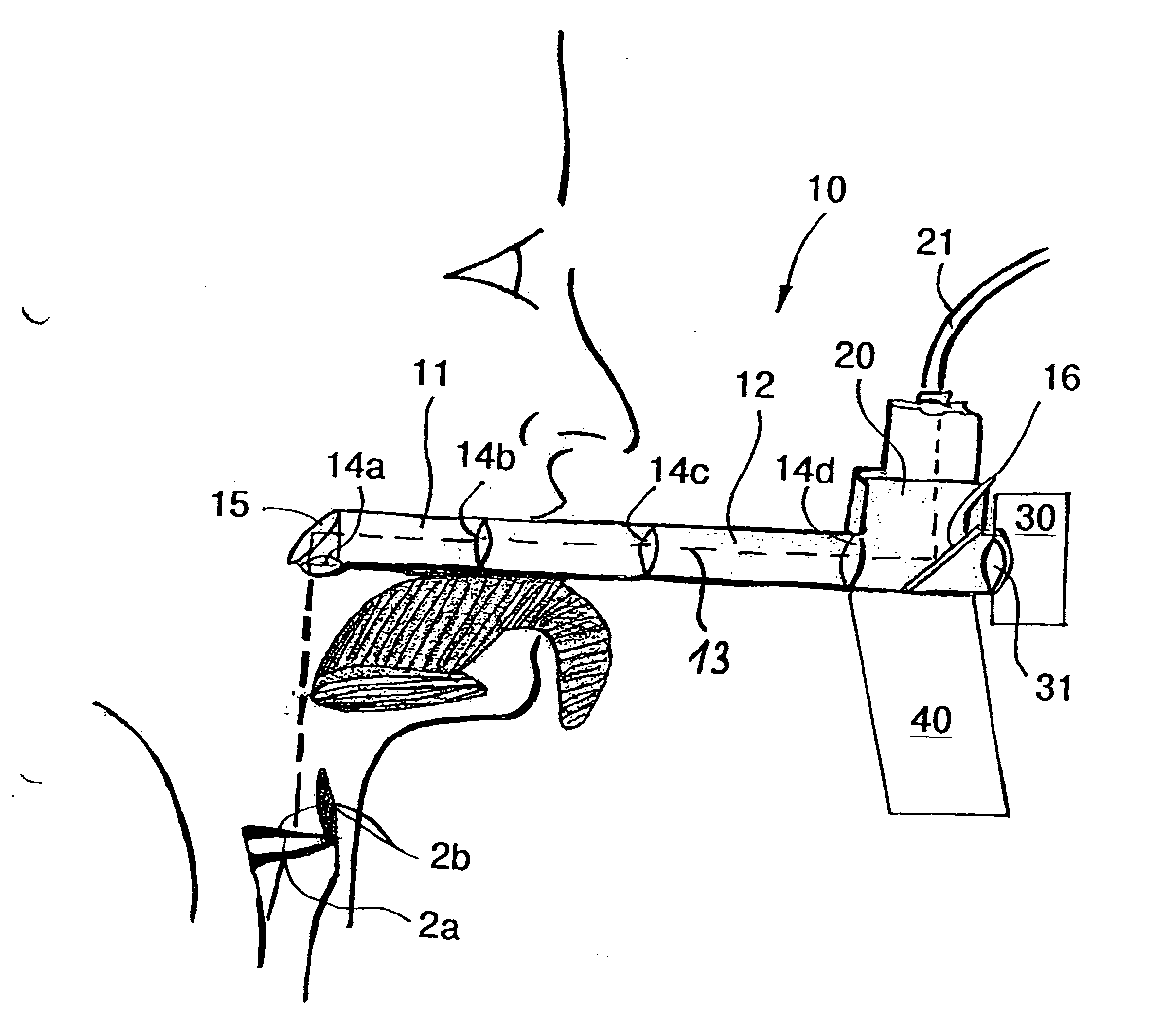
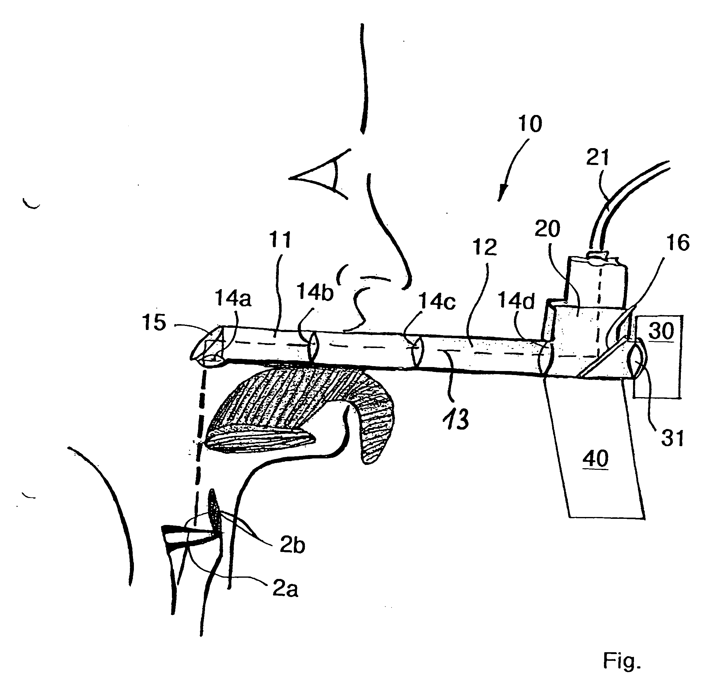
[0014] In a first advantageous embodiment of the invention, the illumination beam path and the imaging beam path run coaxially at least in that portion of the laryngoscope which is insertable into the oral cavity. In this way, the illumination beam source can be coupled into the imaging beam path via a semi-permeable mirror, with the result that the observation device can be configured with a single beam path that can be accommodated within a single fiber optic.

[0015] It is also advantageous when the OCT illumination beam path and the OCT imaging beam path run coaxially at least in that portion of the laryngoscope which is insertable into the oral cavity. In this way, the OCT device of the laryngoscope can be configured with a single beam path that can be accommodated within a single fiber optic.

[0016] It is also advantageous when at least one beam path of the observation device and at least one beam path of the OCT device run coaxially at least in that portion of the laryngoscope...


PUM


Abstract

The invention relates to a laryngoscope with a light guiding portion for insertion into a patient's oral cavity and an observation device for diagnostics with visible light, comprising an illumination beam path for illuminating an examination area with a visible observation beam, and an imaging beam path for guiding the observation beam reflected from the examination area. Such known laryngoscopes permit diagnostics of pathological changes in deeper tissue layers. The laryngoscope of the invention enables this by means of an OCT device for diagnostics using optical coherence tomography, comprising an OCT illumination beam path for illuminating an examination area with the coherent beam, and an OCT imaging beam for guiding the coherent beam reflected from the examination area to an OCT module for generating an image of tissue layers in the examination area.

Description

FIELD OF THE INVENTION [0001] The invention relates to a laryngoscope comprising a light guiding portion for insertion into a patient's oral cavity and an observation device for diagnostics using visible light, an illumination beam path for illuminating an examination area with a visible observation beam, an imaging beam path for guiding the observation beam reflected from the examination area, a first optical aperture through which the observation beam reflected from the examination area enters the laryngoscope, and a second optical aperture for guiding the reflected observation beam to an examiner. BACKGROUND OF THE TECHNOLOGY [0002] Laryngoscopes of the aforementioned kind are used for optical diagnostics in ear, nose and throat medicine, and are used in particular for imaging diagnostics of the vocal folds. For this purpose, the laryngoscope is inserted into the patient's oral cavity and advanced so far in the direction of the pharyngeal cavity that it is possible to observe the...

Claims


Application Information

Patent Timeline
Patent Type & Authority Applications(United States)
IPC IPC(8): A61B5/05A61B1/267A61B1/06
CPCA61B1/00172A61B1/2673A61B5/6852A61B5/0084A61B5/0066
Inventor LUERSSEN, KATHRINLUBATSCHOWSKI, HOLGER
Owner ROWIAK GMBH
Why Eureka
Try Eureka