System for communicating between a master device and each of slave devices

a communication system and slave technology, applied in the field of communication systems, can solve problems such as increasing system manufacturing costs

Inactive Publication Date: 2006-01-26
DENSO CORP
View PDF20 Cites 22 Cited by
  • Summary
  • Abstract
  • Description
  • Claims
  • Application Information

AI Technical Summary

Benefits of technology

[0011] An object of the present invention is to provide, with due consideration to the drawbacks of the conventional communication system, a communication system having a master device and a plurality of slave devices wherein an identifier is automatically assigned to each slave device without increasing manufacturing costs of the communication system.
[0015] Accordingly, different identifiers can be automatically assigned to all slave devices of the communication system, respectively. Further, the communication system can be manufactured at low costs.
[0018] Accordingly, even though the simultaneous outputting of setting response signals or a communication failure occurs in the communication system during the assignment of identifiers to the slave devices, the occurrence of a communication error based on erroneous assignment of identifiers to the slave devices can be prevented.

Problems solved by technology

However, in this communication system of the Publication, a plurality of connectors disposed near the receivers are required to provide the receivers with different IDs, thereby increasing manufacturing costs of the system.

Method used


Image

  • System for communicating between a master device and each of slave devices
  • System for communicating between a master device and each of slave devices
  • System for communicating between a master device and each of slave devices

Examples


embodiment 1

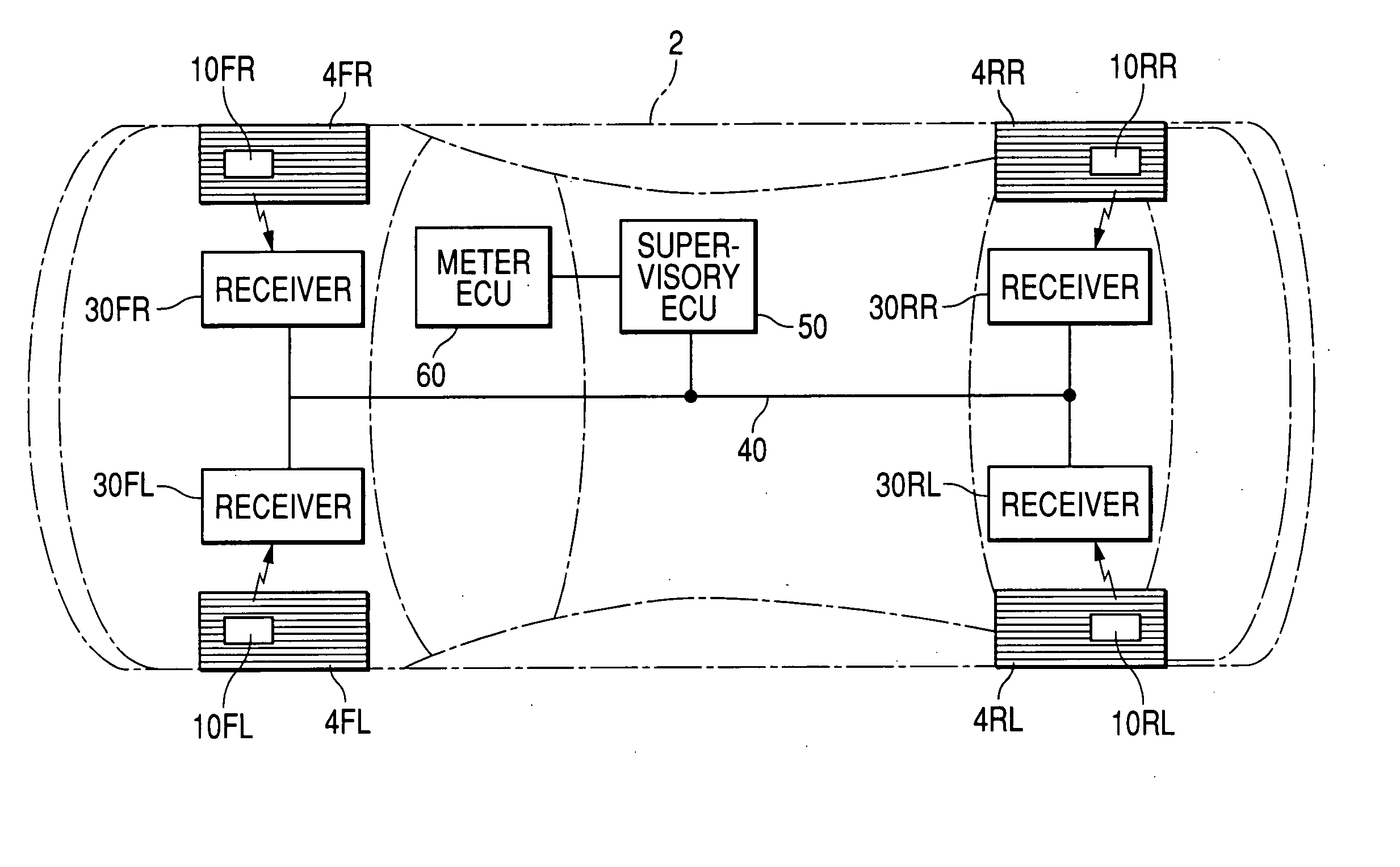
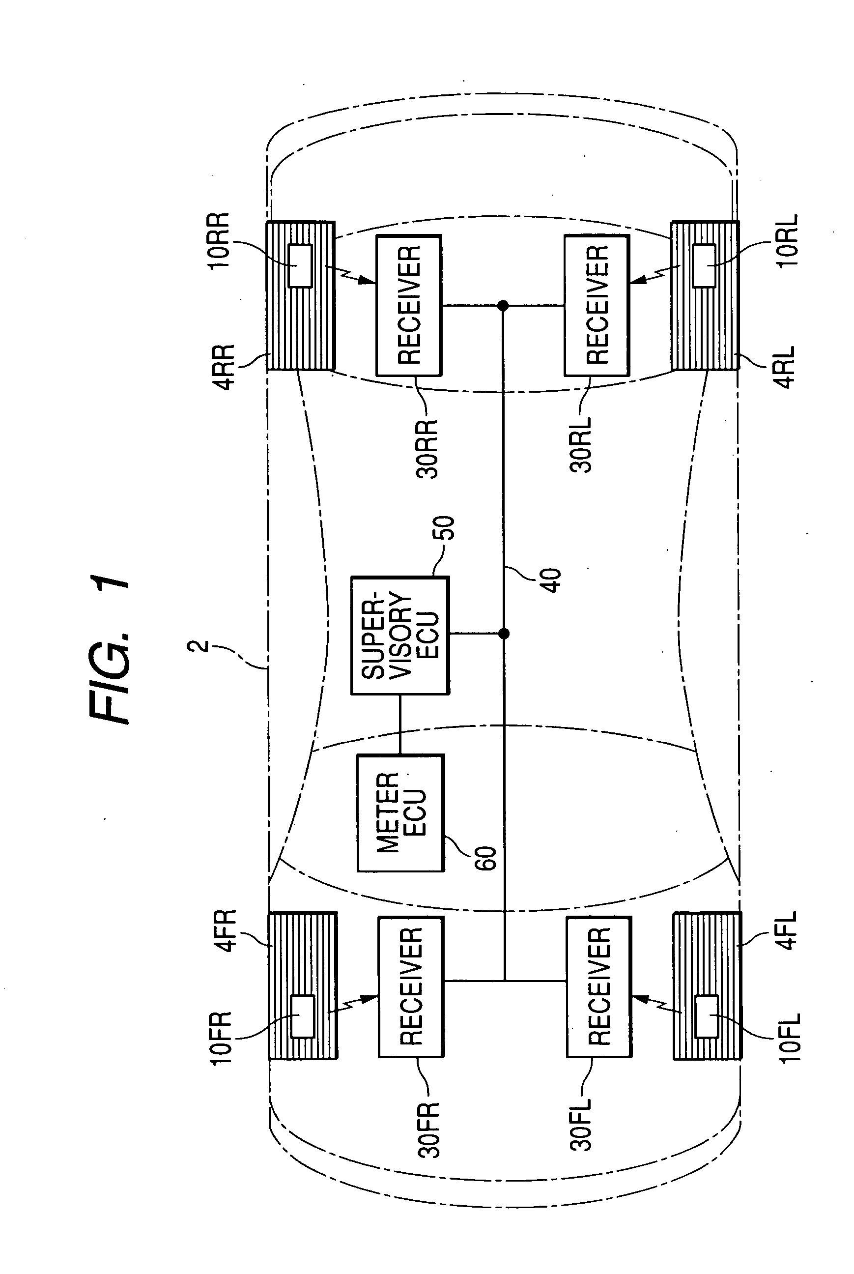
[0042]FIG. 1 is an explanatory view showing the arrangement of a tire condition supervisory system according to first to fourth embodiments of the present invention.

[0043] As shown in FIG. 1, a vehicle 2 has four tubeless tires 4 (4FL, 4FR, 4RL and 4RR) of four wheels (front-left wheel FL, front-right wheel FR, rear-left wheel RL and rear-right wheel RR). A tire condition supervisory system mounted on the vehicle 2 has four detectors 10 (10FL, 10FR, 10RL and 10RR), respectively, disposed into the tires 4, four receivers 30 (30FL, 30FR, 30RL and 30RR), respectively, disposed near the tires 4, a supervisory electronic control unit (ECU) 50, a communication line (or single wire) 40 connecting the receivers 30 with the supervisory ECU 50, and a meter ECU 60.

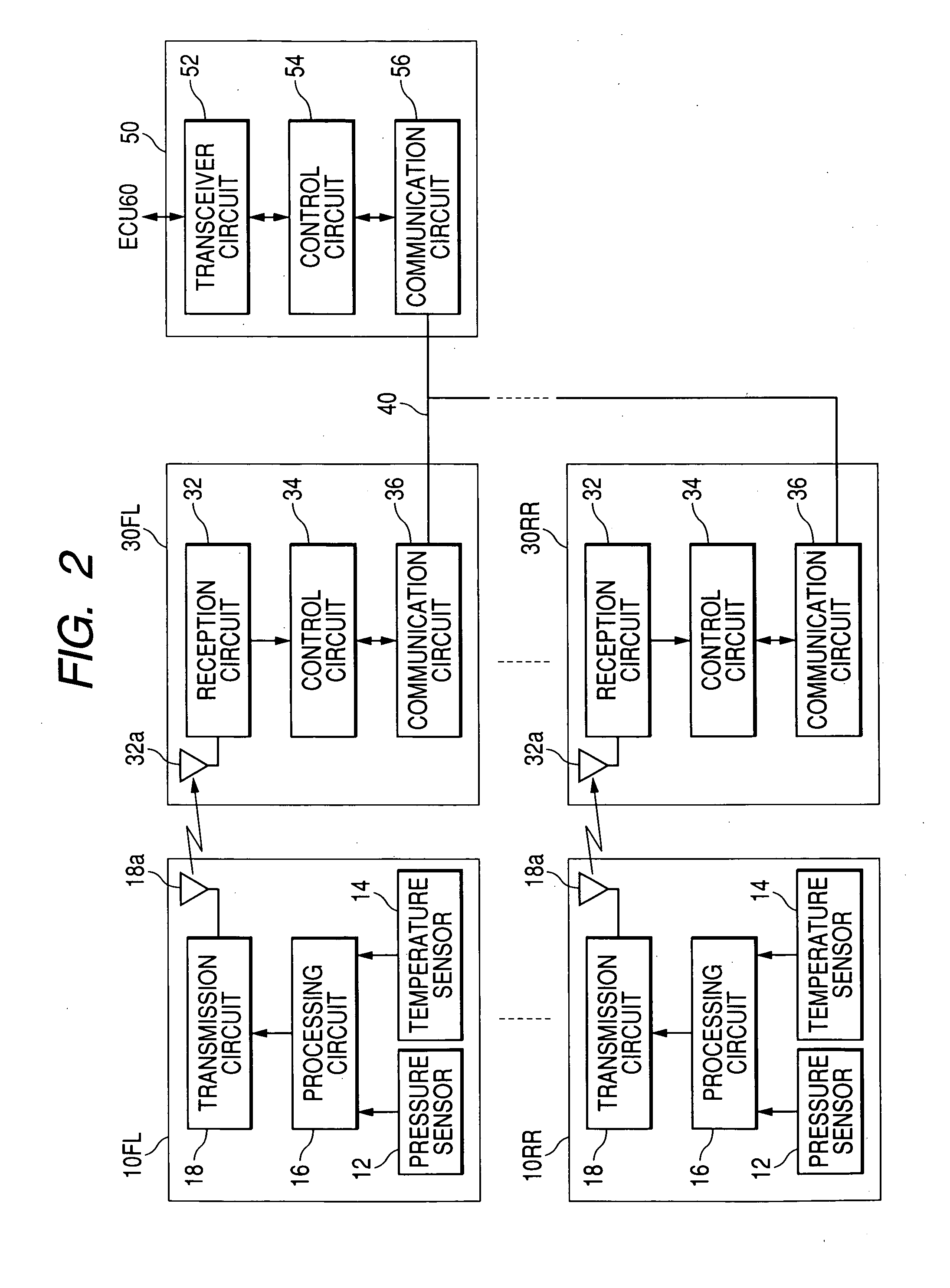
[0044] Each detector 10 detects tire inflation pressure and temperature of air compressed in the corresponding tire 4 every predetermined period of time, and transmits detected values of the inflation pressure and temperature to th...

embodiment 2

[0090]FIG. 5 is a block diagram of each receiver 30 according to a second embodiment of the present invention.

[0091] Each receiver 30 further has two voltage dividing resistors R1 and R2 which divides a source voltage Vcc applied to a terminal of the resistor R1, and an analog-to-digital (A / D) converter 38. Another terminal of the resistor R1 is connected with a terminal of the resistor R2 at a connection point, and another terminal of the resistor R2 is earthed. The A / D converter 38 converts a divided voltage obtained at the connection point into a random variable R, and the control circuit 34 determines a monitoring time period Td from the random variable R.

[0092] The resistors R1 and R2 and a power source circuit of the source voltage Vcc are manufactured with predetermined precision, so that resistance values of the resistors R1 and R2 and the source voltage Vcc in each receiver 30 differ from those of the other receivers 30. Therefore, the monitoring time periods Td different...

embodiment 3

[0094]FIG. 6 is a block diagram of each receiver 30 according to a third embodiment of the present invention.

[0095] Each receiver 30 further has a received signal strength indicator (RSSI) 33 disposed in the reception circuit 32, and the A / D converter 38. The RSSI 33 generates a strength value of a reception signal received at the antenna 32a and indicates the strength of the reception signal. The RSSI 33 outputs a voltage signal indicating the strength value of the reception signal, and the A / D converter 38 converts the voltage signal into a random variable R. The control circuit 34 determines a monitoring time period Td from the random variable R.

[0096] The reception signal received at the antenna 32a is transmitted from the antenna 18a of the corresponding detector 10. Because the antennas 32a of the receivers 30 are disposed at positions different from one another, electro-magnetic conditions for each antenna 32a differ from those for the other antennas 32a. Therefore, the str...


PUM


Abstract

An ECU outputs request signals with different identifiers to a communication line one after another in a manner that one of there quest signals is firstly outputted, and each of the other request signals is outputted when the ECU detects a response signal transmitted through the communication line. Each of receivers independently sets a monitoring period of time, receives the request signals from the communication line and performs an identifier setting judgment every request signal. In this judgment, the receiver monitors the communication line during the monitoring period of time starting upon reception of the request signal unless the receiver has outputted a response signal, outputs a response signal to the communication line when the receiver detects no response signal transmitted through the communication line in the monitoring, and sets an identifier included in the request signal when the receiver outputs the response signal.

Description

CROSS-REFERENCE TO RELATED APPLICATION [0001] This application is based upon and claims the benefit of priority of the prior Japanese Patent Application 2004-159598 filed on May 28, 2004 so that the contents of which are incorporated herein by reference. BACKGROUND OF THE INVENTION [0002] 1. Field of the Invention [0003] The present invention generally relates to a communication system wherein a master device communicates with a plurality of slave devices through a common communication line while identifying each of the slave devices based on an identifier uniquely assigned to the slave device. [0004] 2. Description of Related Art [0005] A communication system such as a local interconnect network (LIN) used, for example, for communication among units of an in-vehicle control system has been known. In this system, a master device is connected with a plurality of slave devices through a common communication line (or single communication line in case of LIN), and each slave device tran...

Claims


Application Information

Patent Timeline
Patent Type & Authority Applications(United States)
IPC IPC(8): G06F15/16G06F7/00H04L12/28H04L12/24H04L12/26H04L12/403
CPCH04L12/403H04L43/10H04L2012/40273H04L2012/40234H04L43/12
Inventor WATABE, NOBUYA
Owner DENSO CORP
Why Eureka
Try Eureka