Leakage current or resistance measurement method, and monitoring apparatus and monitoring system of the same

Inactive Publication Date: 2006-01-26
HITACHI LTD
View PDF11 Cites 33 Cited by
  • Summary
  • Abstract
  • Description
  • Claims
  • Application Information

AI Technical Summary

Benefits of technology

[0023] The present invention provide highly reliable measurement of the resistance component leakage current value and the resistance value and can be used to specify the insulation deteriorati

Problems solved by technology

The above-mentioned method (A) is involved in a problem of incapable of measurement of the resistance component leakage current if the electrostatic capacity is large due to a noise filter because the reactive leakage component current is predominant.
The above-mentioned method (B) is also involved in a problem of complex system structure due to the requirement of external application of a voltage and the requirement of no effect on

Method used


Image

  • Leakage current or resistance measurement method, and monitoring apparatus and monitoring system of the same
  • Leakage current or resistance measurement method, and monitoring apparatus and monitoring system of the same
  • Leakage current or resistance measurement method, and monitoring apparatus and monitoring system of the same

Examples


first embodiment

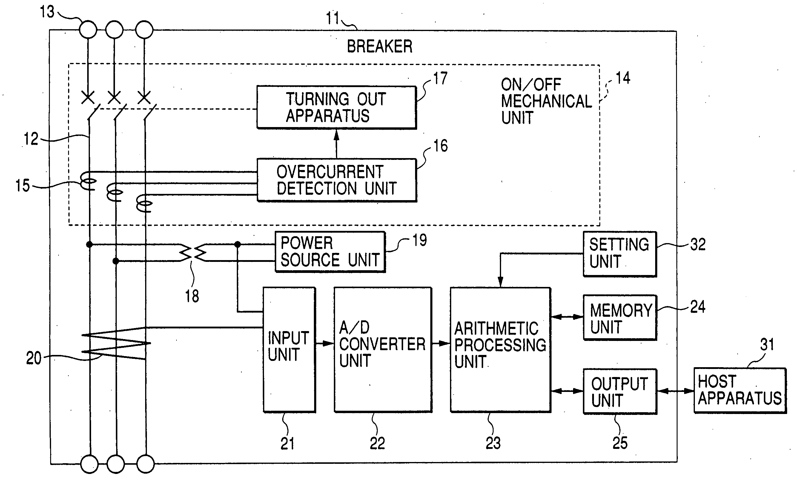
[0045]FIG. 1 is a waveform diagram for describing the leakage current measurement method in accordance with the present invention, and the principle of calculation of the resistance component leakage current from the leakage current by use of this waveform diagram. The waveform shows a waveform for the case that the primary circuit 42 of the distribution system shown in FIG. 9 is a single-phase circuit, in which the output of the current transformer 46 and the voltage waveform generated from the primary circuit 42 are represented by the time axis.

[0046] In FIG. 1, Iz denotes the leakage current, V denotes the voltage, W denotes the leakage current power, and dots of each waveform show the sampling value. The phase of the leakage current Iz proceeds 90 degrees ahead of the voltage if no active component leakage current Igr is involved.

[0047] The power W of the AC circuit is calculated by use of the equation W=VI cos Φ according to the AC theory, wherein V denotes the circuit voltage...

second embodiment

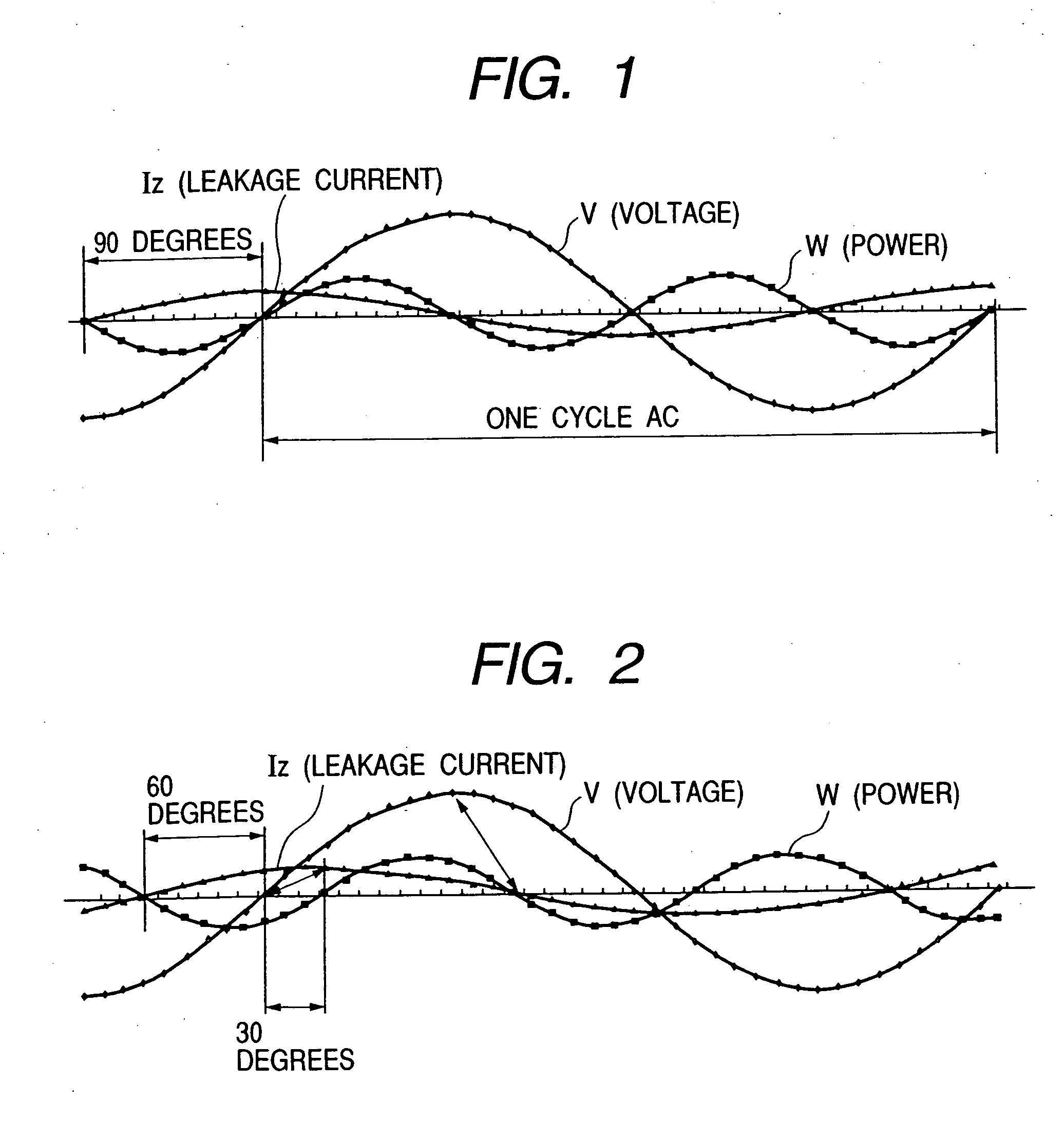
[0051] Next, the present invention will be described with reference to FIG. 2.

[0052]FIG. 2 is a waveform diagram for describing the second embodiment of the leakage current measurement method in accordance with the present invention, and shows the voltage waveform, leakage current waveform, and leakage current power waveform for the case in which the power is supplied to the load with two-wire drawing from the first phase (RS) of the three-phase AC. In this case, the phase of the leakage current Iz proceeds 60 degrees ahead of the voltage (line voltage) if only the electrostatic capacity is involved. The reason is that the line voltage in the three-phase AC proceeds 30 degrees ahead of the phase voltage. Therefore, the second embodiment is characterized in that the instantaneous line voltage value is stored when the leakage current and the line voltage are sampled and the power calculated by use of the instantaneous leakage current value and the stored instantaneous voltage value th...

third embodiment

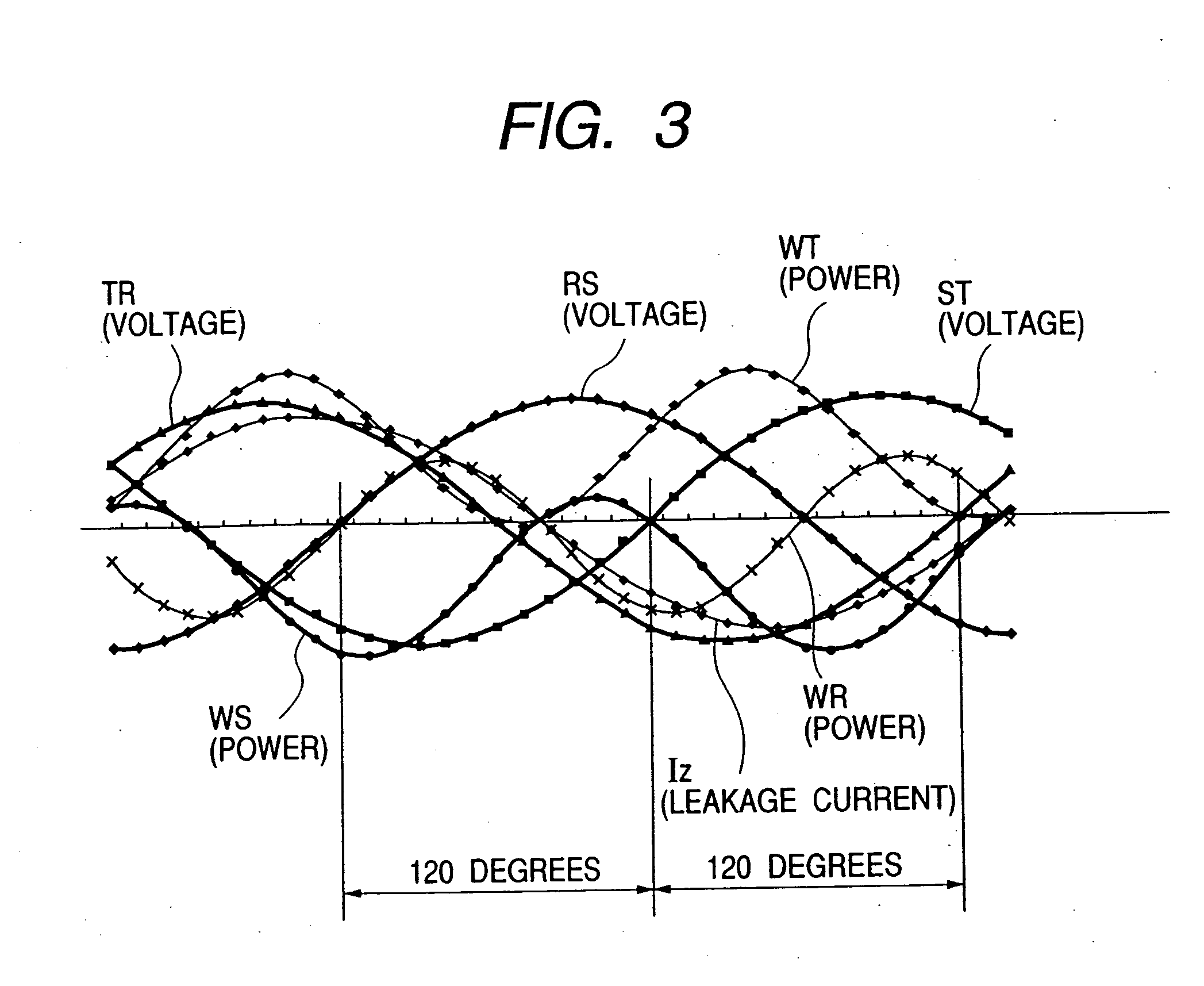
[0053] Next, the present invention will be described with reference to FIG. 3.

[0054]FIG. 3 is a waveform diagram for describing the third embodiment of the leakage current measurement method in accordance with the present invention, and shows the voltage waveform of the three-phase AC (voltage RS, voltage ST, and voltage TR) and the leakage current waveform Iz of the three-phase AC. The voltage of the respective voltage waveforms of the three-phase AC is the line voltage. As it is well known, respective line voltages proceed with intervals of 120 degrees phase difference. When the leakage current is sampled correspondingly to each voltage waveform, the leakage current Iz proceeds 60 degrees ahead of the line voltage as shown in FIG. 3 in the case that only the electrostatic capacity is involved similarly to the second embodiment. Therefore, the instantaneous line voltage values are stored when the leakage current and instantaneous values of each line voltage waveform are sampled, ea...


PUM


Abstract

A measurement method is disclosed for measuring the resistance component leakage current included in the leakage current and the resistance value that is an insulation resistance to monitor the insulation state of a distribution system. The signal waveform of at least one AC cycle is sampled in the resistance component leakage current measurement from the leakage current signal and the voltage signal of a current transformer of target measurement circuit, and the resistance component leakage current is measured by dividing the average of integrated value of the instantaneous leakage current values and the instantaneous voltage values by the square root of average of squared instantaneous voltage values. A zero-cross detecting circuit for detecting a voltage zero-crossing point of the target measurement circuit and outputting a sampling start signal is provided, voltage digital data of the sine wave form whose effective value is 1 and the output signal of the zero-phase current transformer are sampled, and the products of multiplication are averaged by synchronizing the sampled output signal value and the voltage digital data to obtain an active leakage component current of leakage currents.

Description

CROSS-REFERENCES TO RELATED APPLICATIONS [0001] This application is a continuation-in-part application of U.S. application Ser. No. 10 / 856,563, filed May 27, 2004, which is a divisional of U.S. application Ser. No. 10 / 265,040, filed Oct. 4, 2002, which in turn is related to and claims priority from Japanese Application No. 2001-308552, filed Oct. 4, 2001 and Japanese Application No. 2002-272428, filed Sep. 19, 2002, all of which are fully incorporated herein by reference for all purposes.BACKGROUND OF THE INVENTION [0002] This invention relates to a method for measuring the resistance component leakage current included in a leakage current to monitor the insulation of a distribution system, and relates to an instrument, apparatus, or system to which this measurement method is applied. [0003] (A) A direct measurement method in which a zero-phase current transformer is provided to a distribution circuit or a grounding conductor of a transformer, (B) a measurement method in which a vol...

Claims


Application Information

Patent Timeline
IPC IPC(8): G01R19/00
CPCG01R19/2513
Inventor TAKAKAMO, NAOHIROSAKAI, KUNIYOSHITERAKAMI, YOSHIKAZUKAWAUCHI, NOBUYUKI
Owner HITACHI LTD
Why Eureka
Try Eureka