Apparatus and method of enhancing printing press cylinders

a technology of printing press and cylinder, which is applied in the direction of printing press, rotary letterpress machine, printing, etc., can solve the problems of reducing the associated capital investment, damage or deformation of the underlying printing cylinder or print sleeve, and reducing the life of the cylinder, so as to achieve the effect of reducing energy and degrading print quality

Inactive Publication Date: 2006-02-02
NU TECH COATINGS
View PDF30 Cites 12 Cited by
  • Summary
  • Abstract
  • Description
  • Claims
  • Application Information

AI Technical Summary

Benefits of technology

[0010] According to the principles of the present invention, a printing press cylinder is provided having an advantageous construction and method of manufacture. The printing press cylinder includes a rigid base member having a reduced radius section and a polymer layer formed about the rigid base member generally within the reduced radius section. The polymer layer is operable to absorb forces and dissipate energy that degrades print quality. A gear portion is operably coupled to the rigid base member for rotation therewith. The printing press cylinder is manufactured by turning a rigid base member to produce a reduced radius section and subsequently molding a polymer layer generally within the reduced radius section of the rigid base member. The polymer layer is cured and then turned to reduce the circumference thereof and produce a smooth surface.

Problems solved by technology

Unfortunately, such printing systems require a different circumferentially sized printing press cylinder for different final image sizes and further require a separate printing press cylinder and plate assembly for each color to be printed.
As one skilled in the art will appreciate, sleeve interchangeability reduces the need to stock a plurality of printing cylinders and further reduces the associated capital investment.
Unfortunately, these rubber-covered cylinders suffer from a number of disadvantages.
This process can damage or deform the underlying printing cylinder or print sleeve because of the high temperatures.
Furthermore, the vulcanizing process requires cure periods of about a couple hours under pressure to a few days in open air, which adversely effects production throughputs, and finally results in a heavy and cumbersome product that is difficult to handle.
Unfortunately, the use of rubber-covered printing cylinders disrupts this standardization in that the rubber covering is added to an existing printing cylinder, thereby changing its circumference and the corresponding print pitch without changing the corresponding gear system.
This leads to printing systems that require the use of non-standard, and thus expensive, components.
For instance, it has been common for conventional narrow web flexographic printing systems to suffer from gear marking and impression latitude.
More particularly, it is believed that this banding is caused from the non-uniform application of pressure from the printing cylinder onto the printing media as the gear teeth enmesh.
Wide web systems tend not to be effected as severely by such non-uniform application of pressure, perhaps due to the larger contact surface area available to dissipate such energy.
Still further, conventional narrow web systems traditionally suffer from a lack of impression latitude.
However, in conventional narrow web systems there is not typically sufficient area between standard-sized cylinders and standard-sized plates or sleeves to accommodate oversized cushion members.
Additionally, such cushion members are relatively expensive and often break down thereby losing their ability to provide any resiliency in narrow web applications.
This results in high or low spots in the outer printing surface.
The prior art rubber coverings also have a limited impression range.

Method used


Image

  • Apparatus and method of enhancing printing press cylinders
  • Apparatus and method of enhancing printing press cylinders
  • Apparatus and method of enhancing printing press cylinders

Examples


Embodiment Construction

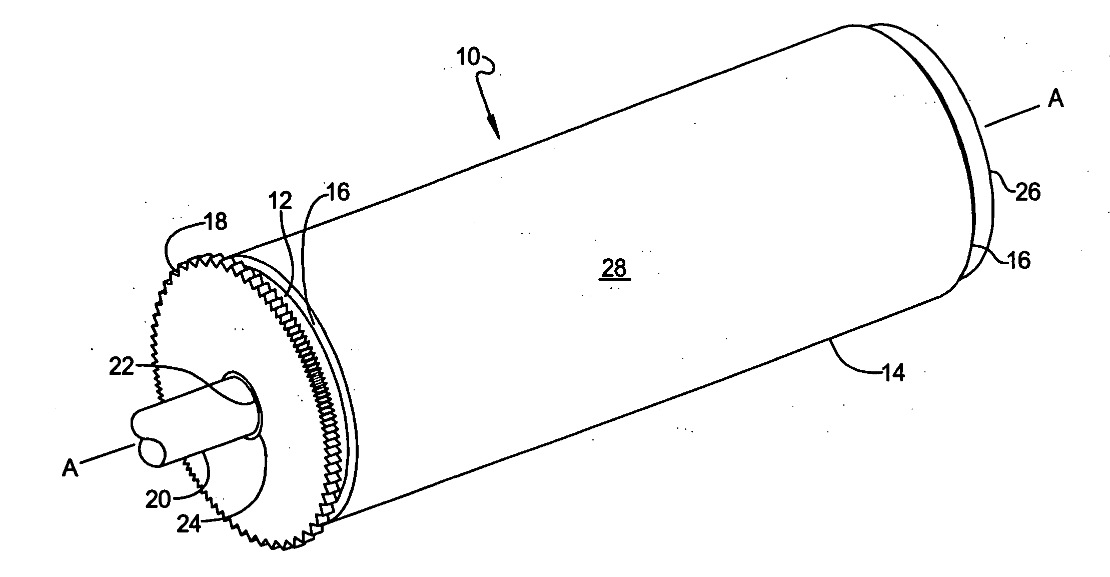
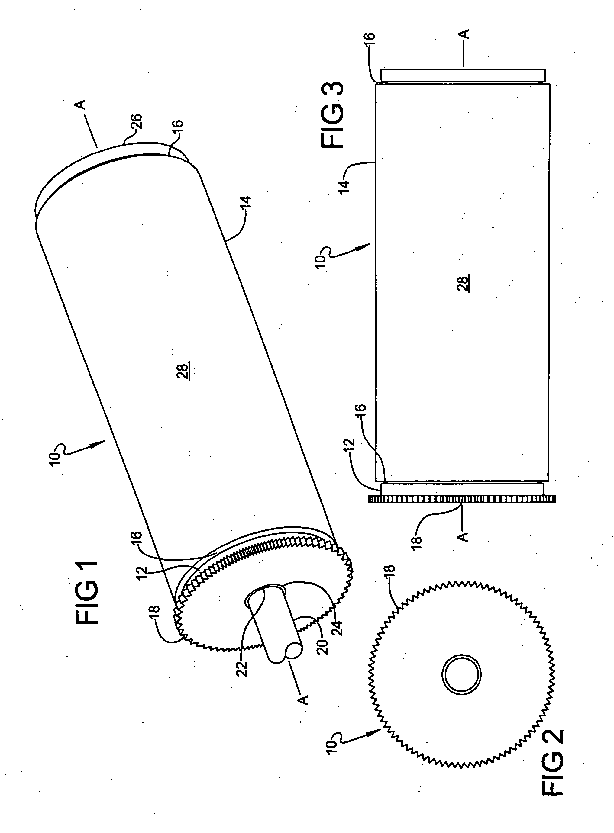
[0022] The following description of the preferred embodiment is merely exemplary in nature and is in no way intended to limit the invention, its application, or uses.

[0023] Referring to FIGS. 1-3, a printing press cylinder, generally indicated at 10, is illustrated in accordance with the principles of the present invention. Printing press cylinder 10 of the present invention provides a number of distinct advantage over the prior art, such as, but not limited to, increased impression latitude, up to about 0.015″; increased production rates; reduced downtime; reduced setup time; reduced gear marking; reduced dot gain; reduced slur; and improved product consistency. These benefits, in addition to many others, are achieved through the novel construction of printing press cylinder 10. These benefits are particularly advantageous in the cost-constrained narrow web printing industry; however, these benefits are equally applicable to wide web printing applications. Therefore, the discussio...


PUM


Abstract

A printing press cylinder and a method of manufacturing the same. The printing press cylinder includes a rigid base member having a reduced radius section and a polymer layer formed about the rigid base member generally within the reduced radius section. The polymer layer is operable to absorb forces and dissipate energy that degrades print quality. A gear portion is operably coupled to the rigid base member for rotation therewith. The printing press cylinder is manufactured by turning a rigid base member to produce a reduced radius section and subsequently molding a polymer layer generally within the reduced radius section of the rigid base member. The polymer layer is cured and then turned to reduce the circumference thereof and produce a smooth surface.

Description

FIELD OF THE INVENTION [0001] The present invention relates to printing press cylinders and, more particularly, relates to printing press cylinders capable of enhancing print quality. BACKGROUND OF THE INVENTION [0002] In the printing industry, flexographic printing systems are often used as an economical alternative to higher-priced printing systems, such as offset and rotogravure printing. Flexographic printing systems typically include a flexographic printing plate formed from a flat substrate that is deformed and mounted to a printing press cylinder. A raised image may be formed on the printing plate either before or after the printing plate is attached to the printing press cylinder. Unfortunately, such printing systems require a different circumferentially sized printing press cylinder for different final image sizes and further require a separate printing press cylinder and plate assembly for each color to be printed. As one can readily appreciate, large printing plants must ...

Claims


Application Information

Patent Timeline
Patent Type & Authority Applications(United States)
IPC IPC(8): B41F5/00
CPCB41F13/10B41P2200/12B41F13/193
Inventor BRUNST, GEORGE E.
Owner NU TECH COATINGS
Why Eureka
Try Eureka