Point-of-use water treatment system

a technology of point-of-use water treatment and water treatment system, which is applied in the direction of multi-stage water/sewage treatment, other chemical processes, separation processes, etc., can solve the problems of heat build-up inside and outside the filter housing of the wts unit, increase the temperature of water stored within the wts unit, and difficult to remove or install the filter closure from or on the wts unit filter housing, etc., to achieve easy and quick installation and removal. ,

Inactive Publication Date: 2006-02-02
ACCESS BUSINESS GRP INT LLC
View PDF56 Cites 66 Cited by
  • Summary
  • Abstract
  • Description
  • Claims
  • Application Information

AI Technical Summary

Benefits of technology

[0015] The present invention includes a WTS unit which has a unique filter closure and attachment mechanism that allows the closure to be easily and quickly secured to and removed from a filter housing. The filter housing has a filter chamber for receiving a filter. The closure releasably seals with the housing assembly to form a closed pressure vessel. The attachment mechanism is ideally attached to the closure and utilizes a mechanical advantage, preferably in the form of a pivoting handle which cams a pair of reciprocating lock blades into and out of engagement with one or more blade receiving openings on the filter is housing.
[0016] The present invention also covers a WTS unit having a UV tank assembly, a UV bulb assembly received within the UV tank, and a heat dissipating support plate juxtaposed the UV tank assembly. This arrangement allows heat generated by the UV bulb assembly and transferred to the UV tank to be readily transferable to the support plate and then the atmosphere. Use of the heat dissipating support plate also allows low strength decorative outer housing components to be used with the WTS unit as the support plate provide structural support to internal components and for wall mounting of the WTS unit.

Problems solved by technology

A first problem many WTS units encounter is that filter closures can be difficult to remove from or install on WTS unit filter housings.
After water has not been run through a WTS unit for a significant period of time, such as overnight, heat from the UV bulb and other electrical circuitry can cause heat to build up inside and elevate the temperature of water stored within the WTS unit.
The resulting increased temperature contributes to plastic creep and the “welding” together of the threads on the filter closure and filter housing.
Because of the large area of contact between the threads, considerable force may be required to break the “weld” on the threads and release the closure from the filter housing.
A problem with this type of mount is that a filter closure must be accurately aligned with a housing to effect mounting of the filter closure to the filter housing.
Also, even with a bayonet mount, there is still significant joint contact area between the filter closure and the filter housing.
Again, significant force may be required to break the filter closure free from the filter housing after a long period of attachment.
A second problem associated with WTS units having UV bulbs is the build up of heat within the WTS units.
Adverse consequences related to elevated temperature include structural degradation of plastic components over time due to creep, discoloration of plastic components, and decreased reliability of electrical circuitry.
Also, the temperature of water stored overnight within a WTS unit can become uncomfortably warm to the touch when discharged from the WTS unit.
Accordingly, expensive specialty plastics may be required in making such outer housings.
A third problem associated with WTS units having UV bulbs is that UV bulbs are cumbersome to change.
The UV bulbs have a limited lifetime and must be periodically changed.
While the UV light emitted by the bulbs is beneficial in destroying chemical bonds in microorganisms, hence severely inhibiting their ability to replicate or reproduce, the UV light can also be harmful to human eyes.
A fourth problem common to WTS units having UV light disinfection is that water flowing through a UV tank assembly may not be uniformly treated or exposed to UV light.
Without steady or plug flow through the UV tank assembly, this objective cannot be optimally met.
However, the Teflon coils can deteriorate and / or cloud over.
Also, the Teflon coils can be damaged by heat.
Further, water borne contaminants may reduce the transmissibility of light through the Teflon coils over time.
While this UV tank assembly design provides satisfactory flow characteristics, the tank is expensive and difficult to manufacture due to numerous deep drawing operations required to form the tank.
Further, there are numerous machining operations which must be performed on stainless steel components which also increases the complexity and cost of manufacture.
Another drawback conventional WTS units have is the use of a plurality of tubes to fluidly interconnect the various components of the WTS units.
The large number of tubes used makes assembly inconvenient and time consuming.
Further, tubes can become brittle over time and may eventually have to be replaced.
With this complexity of tubes and tube clamps, replacement of parts is difficult for the average consumer.
Moreover, designs utilizing tubes makes optimization of the compactness of a WTS unit difficult.

Method used


Image

  • Point-of-use water treatment system
  • Point-of-use water treatment system
  • Point-of-use water treatment system

Examples


Embodiment Construction

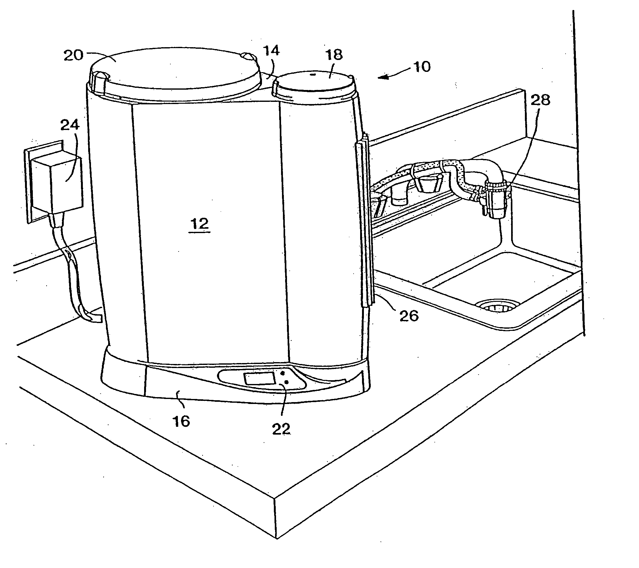
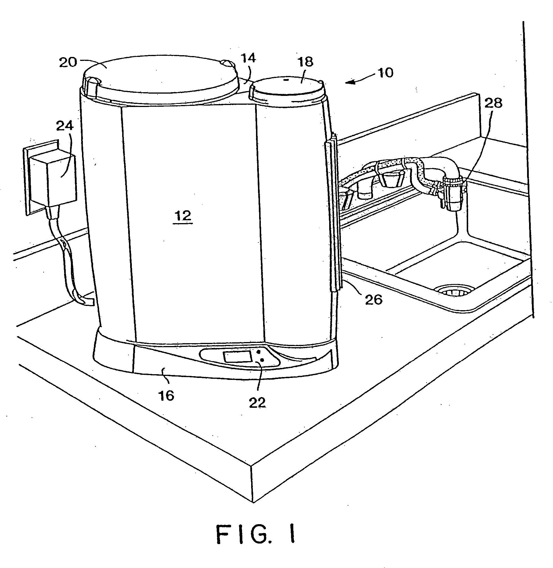
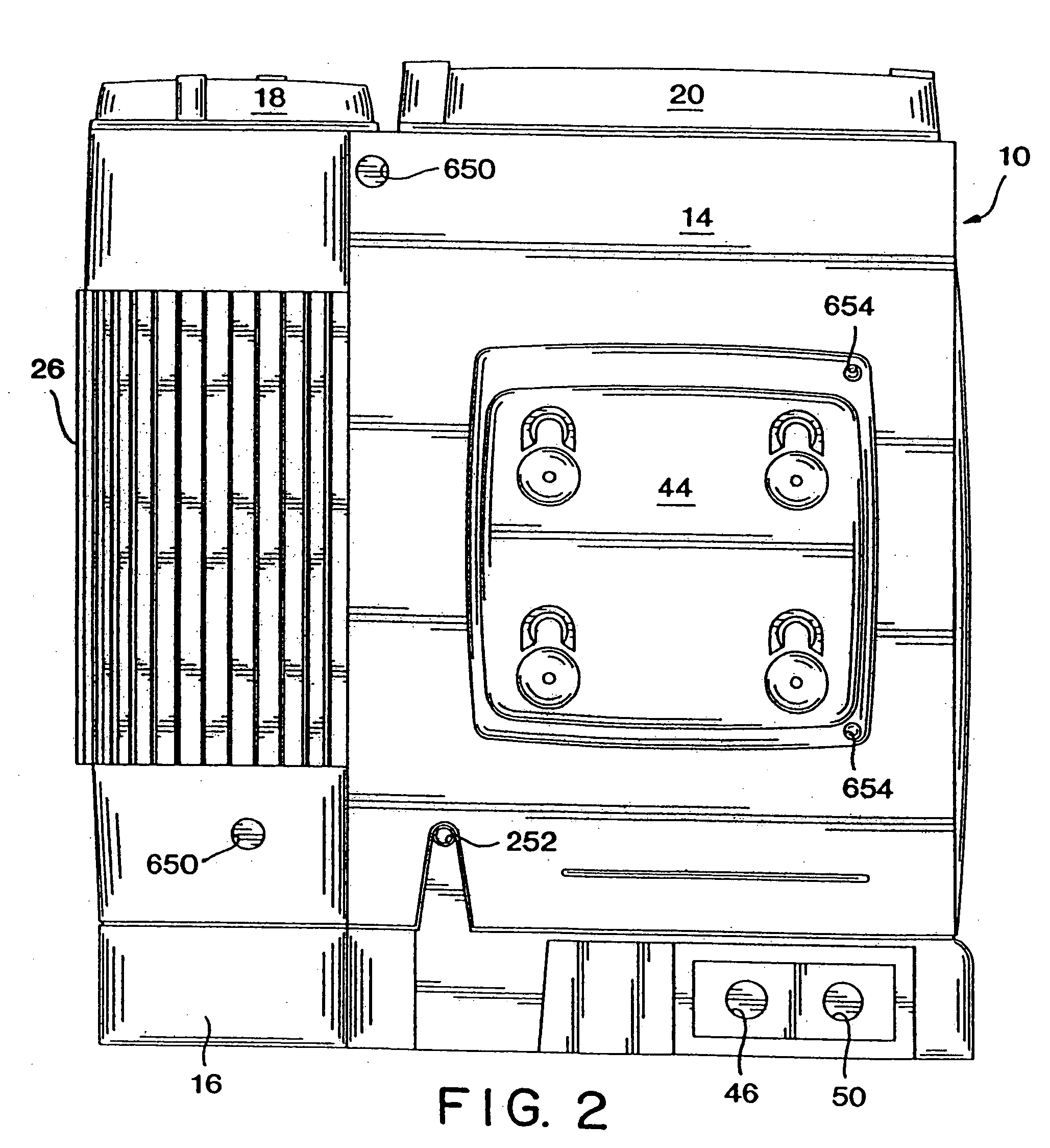
[0048]FIGS. 1 and 2 show a WTS (water treatment system) unit 10 made in accordance with the present invention. WTS unit 10 uses carbon block filtration to filter particles and remove certain chemical contaminants from water. A UV light system is employed to destroy microorganisms. A monitor is used to report on the status of the filtration and the UV light systems.

[0049] WTS unit 10 includes a front outer housing 12, a rear outer housing 14, and a flow monitor assembly 16 which also serves as the base for the WTS unit 10. Located atop front and rear outer housings 12 and 14 are decorative bulb and filter covers 18 and 20. A monitor 22 is mounted in flow monitor assembly 16 which will be further described below. A power supply 24, in the form of a transformer, provides electrical power to WTS unit 10. A finned aluminum support plate 26 extends through an opening in rear outer housing 14 and facilitates the dissipation of heat from within WTS unit 10. A faucet diverter valve assembly...


PUM

PropertyMeasurementUnit
angleaaaaaaaaaa
anglesaaaaaaaaaa
anglesaaaaaaaaaa

Abstract

The present invention relates to a point-of-use water treatment system unit (10). The unit (10) includes a filter housing assembly (60) having a filter tank assembly (66) and a closure (64) which utilizes a handle (152) and cammed reciprocating lock blades (146, 150) to secure the closure (64) to the filter tank assembly (66). A UV tank assembly (300) includes a planar baffle plate (322) and a vaned baffle plate (324) to induce plug flow about a UV lamp assembly (280). The UV lamp assembly (280) is used which simultaneously electrically and sealingly mounts to UV tank assembly (300) and electrical cap assembly (290) using a bayonet mount. A bi-planar manifold assembly (40) is used to interconnect components of the WTS unit and to provide an envelope for accommodating a water pipe assembly (34). The bi-planar manifold assembly (26) enhances the compactness of the design of the WTS unit (10). Also, a support plate (26) is disclosed which provides support to subcomponents of the WTS unit (10) while also dissipating heat from a UV tank assembly (300).

Description

RELATED APPLICATIONS [0001] This is a continuation of application Ser. No. 10 / 234,347, filed Sep. 4, 2002 (now U.S. Pat. No. ______), which is a division of prior application Ser. No. 09 / 744,844, filed as PCT / US99 / 17374 on Jul. 30, 1999 (now U.S. Pat. No. 6,533,930), which is the National Stage of International Application No. PCT / US99 / 17374, filed Jul. 30, 1999, which is continuation-in-part of U.S. application Ser. No. 09 / 299,053, filed Apr. 23, 1999 (now U.S. Pat. No. 6,245,229). INCORPORATION BY REFERENCE [0002] This application hereby incorporates by reference U.S. Pat. No. 5,536,395 and claims priority to provisional application Ser. No. 60 / 094,918, filed on Jul. 31, 1998.TECHNICAL FIELD [0003] The present invention relates to point-of-use water treatment systems (WTS) units for above or below countertop use in homes or offices for the purposes of removing contaminants from water. BACKGROUND OF THE INVENTION [0004] The present invention minimizes or overcomes several problems ...

Claims


Application Information

Patent Timeline
Patent Type & Authority Applications(United States)
IPC IPC(8): C02F1/32C02F9/12B01D35/30A61L2/10C02F9/00
CPCA61L2/10B01D29/96C02F2307/04C02F2301/026B01D35/30B01D2201/291B01D2201/301C02F1/004C02F1/008C02F1/283C02F1/32C02F1/325C02F9/00C02F9/005C02F2201/006C02F2201/3223C02F2201/328C02F2301/024C02F1/001C02F9/20
Inventor WOODARD, JAMES A. JR.ABEREGG, DALESNYDER, GREG
Owner ACCESS BUSINESS GRP INT LLC
Why Eureka
Try Eureka