Motor Stator and Motor
a stator and motor technology, applied in the direction of dynamo-electric machines, electrical apparatus, windings, etc., can solve the problems of limiting the improvement of the slot-fill factor of the coil, the failure of the conductor, etc., to prevent the separation of the conductor, reduce the thickness of the coil, and build coils smoothly
- Summary
- Abstract
- Description
- Claims
- Application Information
AI Technical Summary
Benefits of technology
Problems solved by technology
Method used
Image
Examples
first embodiment
Overall Motor Structure
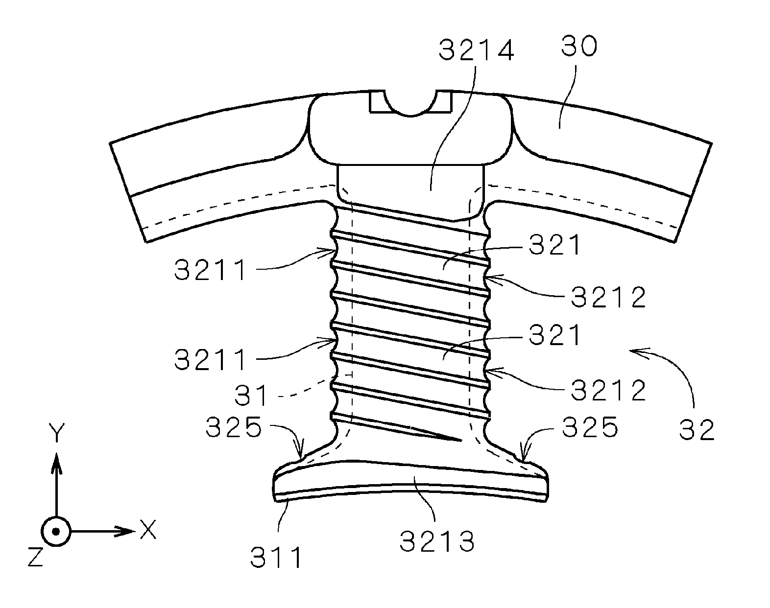
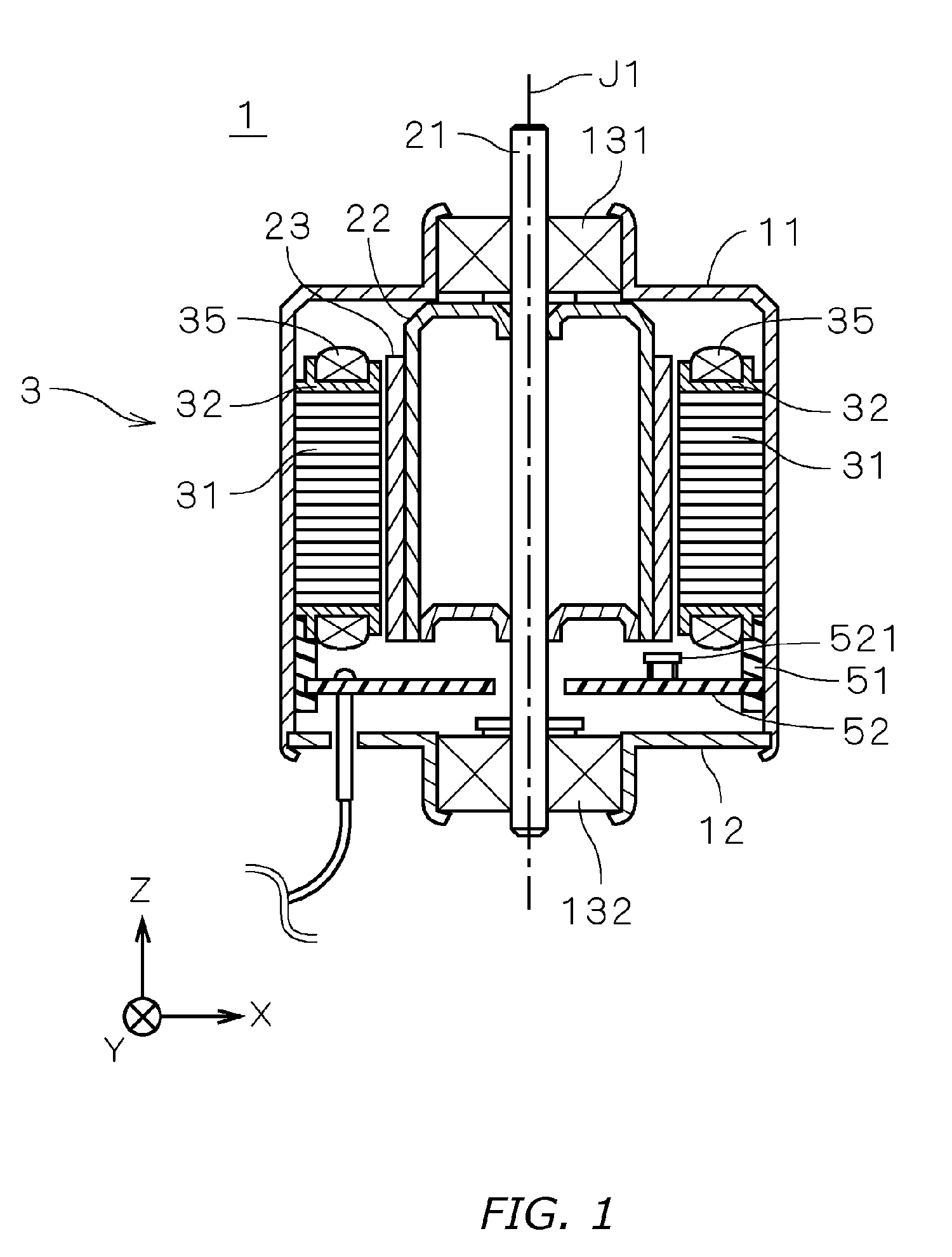
[0031]FIG. 1 is a vertical section showing an electric inner rotor-type motor 1 according to a first embodiment of the present invention. In the diagram, the motor 1 is covered by a cylindrical housing 11 with a small opening on the (+Z) side and a large opening on the (−Z) side in the diagram, and by a cover plate 12, which covers all but the center section of the opening on the (−Z) side. Ball bearings 131, 132 are fit respectively onto the housing 11 (+Z) side opening and onto the cover plate 12 opening, and a shaft 21 is rotatably supported by the ball bearings 131, 132. In the explanation that follows, the (+Z) and (−Z) sides along the motor 1 center axis J1 are respectively described as the upper and lower sides for the sake of convenience, but there is no requirement that the center axis J1 necessarily conform to the direction of gravity.
[0032] A cylindrical rotor yoke 22 is attached to the shaft 21 inside the housing 11, and a multipole magnetized f...
second embodiment
[0075]FIGS. 14 and 15 are respectively a plan view and a bottom view showing the region of an insulator 32 in a motor stator according to a second embodiment of the present invention. In a motor according to the second embodiment, a plurality of insulators 32a is disposed in place of the plurality of insulators 32 shown in FIG. 1. Other structures are the same as in FIG. 1, and the same reference numerals are used in the explanation below.
[0076] In a motor according to a second embodiment, as with the motor 1 according to the first embodiment, insulators 32a are provided with a first partition 323 and a second partition 324 respectively attached on the (+Z) side and the (−Z) side of the teeth 31 (cf. FIG. 6). A plurality of first guide grooves 321 is formed at the upper end portion of the first partition 323, and a plurality of second guide grooves 322 is formed at the lower end portion of the second partition 324.
[0077] As shown in FIGS. 14 and 15, the difference in radial distan...
third embodiment
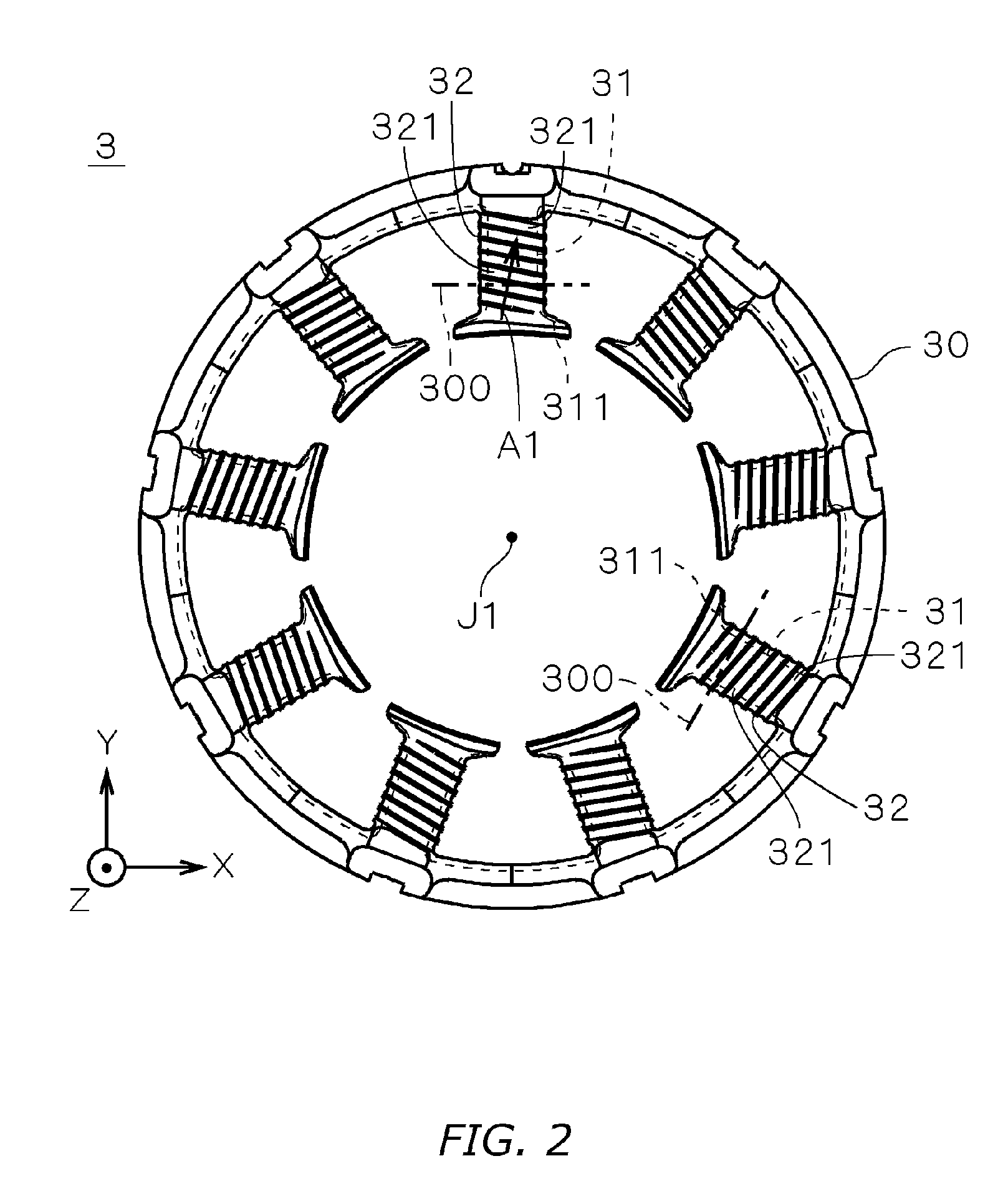
[0082]FIGS. 16 and 17 are partially sectional views showing one insulator's first partition 323a and second partition 324a in a motor stator according to a third embodiment of the present invention. The “”shaded area indicated by parallel slanted lines, as in FIGS. 8 and 9, is a section through an imaginary plane 300 (cf. FIG. 2) which is parallel to the center axis J1 and perpendicular to the teeth 31. Each of the insulators in the motor according to the third embodiment is the same as those in FIG. 1 with the exception that the sectional shape of the end section differs slightly in the direction parallel to the center axis J1. The same reference numerals are used in the explanation below.
[0083] As shown in FIG. 16, in the first partition 323a, a first crown section 3232, which is the most (+Z)-ward, distal edge of the end portion on the partition side where the first guide grooves 321 are formed, is positioned closer to the end point side than the start point side of the conducto...
PUM
 Abstract
Description
Claims
Application Information
 - R&D
- Intellectual Property
- Life Sciences
- Materials
- Tech Scout
- Unparalleled Data Quality
- Higher Quality Content
- 60% Fewer Hallucinations
Browse by: Latest US Patents, China's latest patents, Technical Efficacy Thesaurus, Application Domain, Technology Topic, Popular Technical Reports.
© 2025 PatSnap. All rights reserved.Legal|Privacy policy|Modern Slavery Act Transparency Statement|Sitemap|About US| Contact US: help@patsnap.com


