
Versatile attenuator

a reverse attenuator and oscillator technology, applied in the direction of code conversion, automatic control, instruments, etc., can solve the problems of inability to achieve the dynamic range of the receiver above 60 db, the effect of enhancing the effective dynamic range of the accompanying circuit and facilitating the reverse attenuation

Inactive Publication Date: 2006-02-02
RAYTHEON CO
View PDF13 Cites 17 Cited by
  • Summary
  • Abstract
  • Description
  • Claims
  • Application Information

AI Technical Summary

Benefits of technology

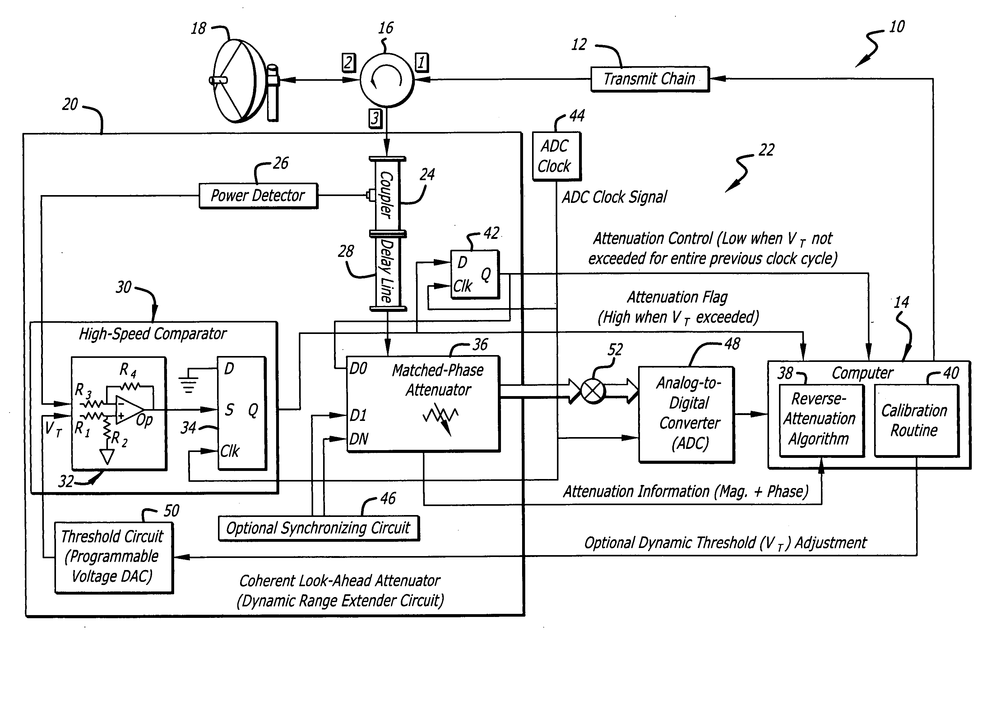
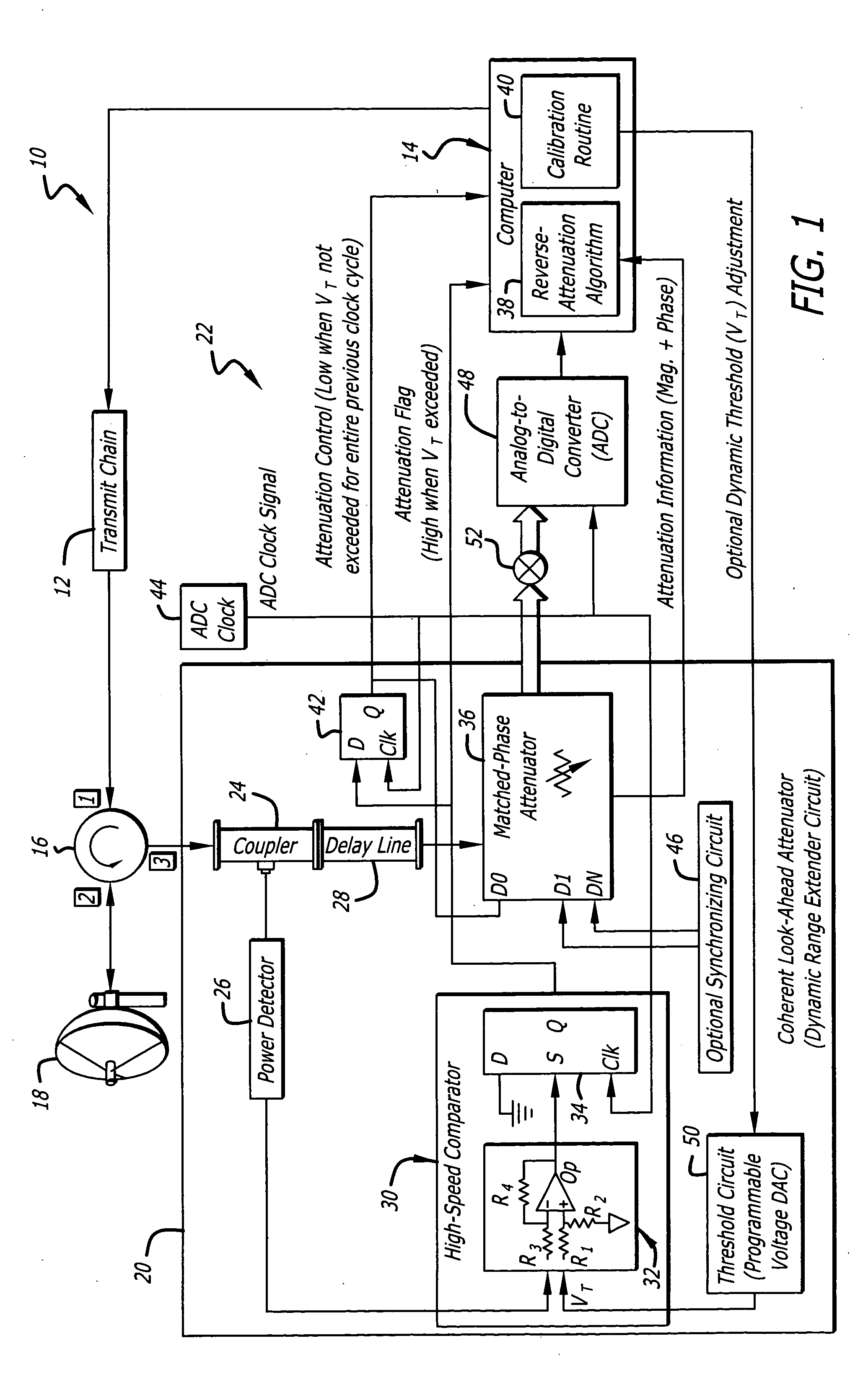
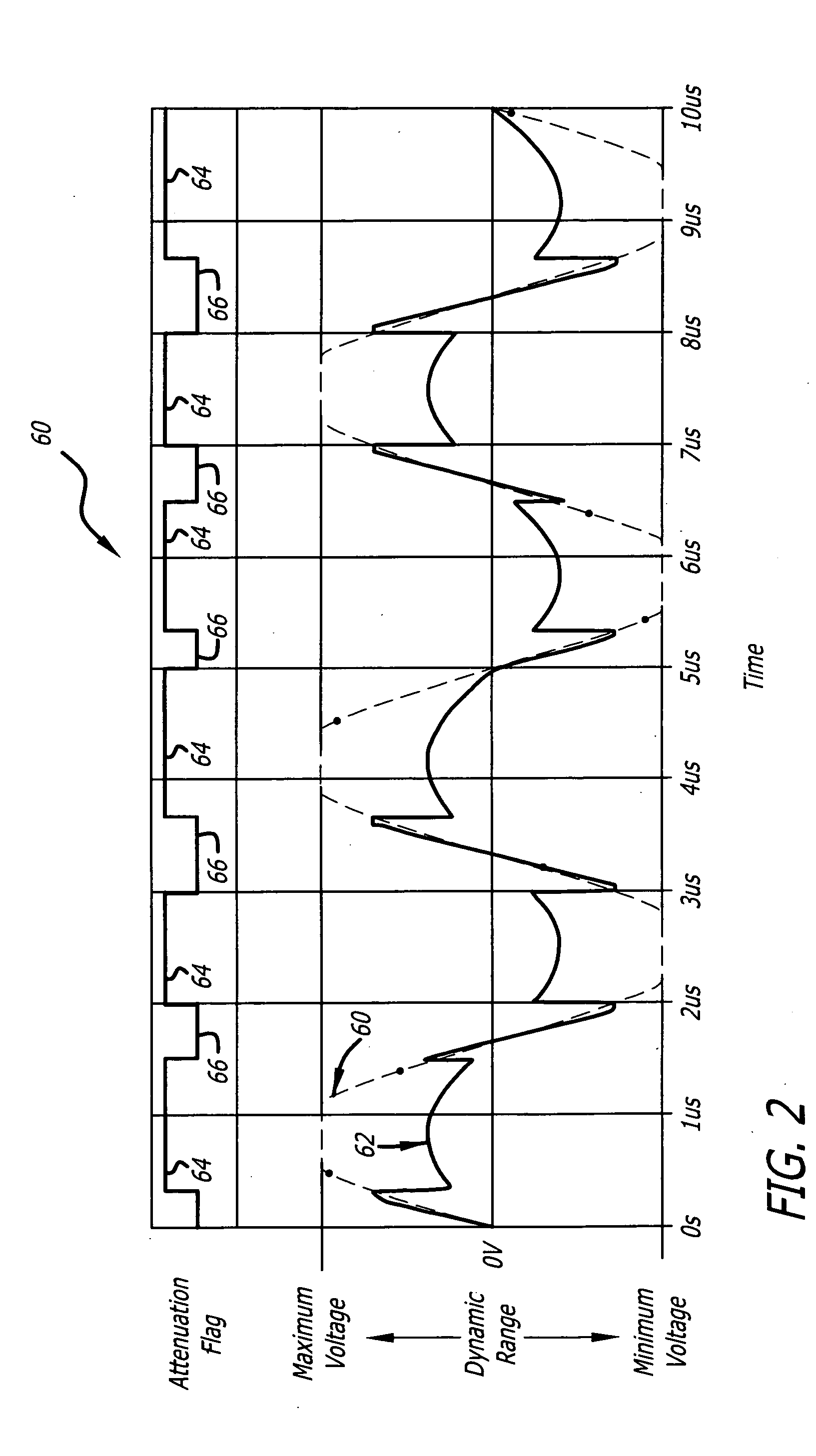
[0014] The novel design of one embodiment of the present invention is facilitated by the second and third mechanisms, which selectively attenuate portions of the receive signal characterized by signal levels that would otherwise exceed the dynamic range of the accompanying ADC or other circuit. By flagging portions of the receive signal for attenuation at particular intervals and incorporating a sufficient delay in the receive signal so that the receive signal and the attenuation flags are synchronous, attenuation can be readily removed by a computer from the signal after processing by the ADC or other circuit. This greatly enhances the effective dynamic range of the accompanying circuit. Attenuation factors and phase information are maintained and forwarded to the computer to facilitate performing reverse attenuation on the receive signal. Hence, valuable signal magnitude and phase information are maintained while effective circuit dynamic range capabilities are enhanced. The unique system acts as a coherent look-ahead attenuator for extending the dynamic range of a circuit.

Problems solved by technology

Unfortunately, dynamic ranges of ADC's are improving somewhat slowly.
Furthermore, high dynamic range ADC's require accompanying high-performance components, such as mixer / amps, which may be prohibitively expensive or unavailable.
Accordingly, conventional receiver design methods are often incapable of achieving receiver dynamic ranges above 60 dB.
Unfortunately, lowering video levels may compromise receiver ability to detect faint signals and to extract desired signals from background noise or ground clutter.
An AGC automatically adjusts average receive signal levels to avoid frequent ADC saturation and associated signal spurs, which compromise receiver performance.
Unfortunately, valuable signal magnitude information is often lost by AGC video adjustment.
For example, the original magnitude of a large attenuated input signal may be unknown after attenuation, and faint signals among large signals may become undetectable.
AGC's typically do not increase the effective dynamic range of accompanying ADC's.
Unfortunately, the sliding scale attenuator is relatively slow, cannot optimize the dynamic range of the ADC, and causes loss of signal magnitude information.

Method used


Image

  • Versatile attenuator
  • Versatile attenuator
  • Versatile attenuator

Examples


Embodiment Construction

[0018] While the present invention is described herein with reference to illustrative embodiments for particular applications, it should be understood that the invention is not limited thereto. Those having ordinary skill in the art and access to the teachings provided herein will recognize additional modifications, applications, and embodiments within the scope thereof and additional fields in which the present invention would be of significant utility.

[0019]FIG. 1 is a diagram of a transceiver 10 employing an efficient coherent look-ahead attenuator 20 according to an embodiment of the present invention. For clarity, various features, such as power supplies, automatic gain control circuits, computer operating systems, and so on, have been omitted from the figures. However, those skilled in the art with access to the present teachings will know which components and features to implement and how to implement them to meet the needs of a given application.

[0020] In the present speci...


PUM


Abstract

A versatile attenuator. The versatile attenuator includes a first mechanism for receiving an input signal. A second mechanism measures the input signal and provides a signal-level indication in response thereto. A third mechanism selectively attenuates the input signal when the signal-level indication surpasses a predetermined threshold and provides an attenuated signal in response thereto. In a more specific embodiment, the third mechanism further provides attenuation information. An additional mechanism then employs the attenuation information and a computer to selectively adjust an output signal of a circuit connected between the computer and the third mechanism to accommodate effects that attenuation of the input signal by the third mechanism has on the output signal.

Description

BACKGROUND OF THE INVENTION [0001] 1. Field of Invention [0002] This invention relates to electrical and electronic circuits and systems. Specifically, the present invention relates to systems and methods for improving the dynamic range of circuits, such as radar and Radio Frequency (RF) communications receivers. [0003] 2. Description of the Related Art [0004] Receivers are employed in various demanding applications including radar, ladar, and microwave sensing systems. Such applications demand receivers that can accommodate various signal magnitudes including both faint and intense signals without causing signal distortion, such as spurs, clipping, or intermodulation distortion. This necessitates receivers with high dynamic ranges, preferably above 100 dB. High dynamic range receivers are particularly important in communications systems and projected munition targeting applications, where sufficient system resolution and signal detection capability are required to extract desired s...

Claims


Application Information

Patent Timeline
Patent Type & Authority Applications(United States)
IPC IPC(8): H03L5/00
CPCG01S7/34H03M1/183H03G3/3073H03G3/3068
Inventor DWELLY, WESLEYADAMS, VINH N.
Owner RAYTHEON CO
Learn More