Optical tomography of small objects using parallel ray illumination and post-specimen optical magnification

a technology of optical tomography and parallel ray illumination, applied in the field of optical tomography (ot) imaging systems, can solve the problems of limited signal to noise ratio that can be achieved, high cost, and inability to meet the requirements of the patient, etc., and achieve the effect of reducing the cost of patient care and patient care, and improving the quality of patient car

Inactive Publication Date: 2006-02-02
VISIONGATE
View PDF77 Cites 74 Cited by
  • Summary
  • Abstract
  • Description
  • Claims
  • Application Information

AI Technical Summary

Benefits of technology

[0011] The present invention provides a shadowgram optical tomography system for imaging an object of interest. The shadowgram optical tomography system includes a parallel ray light source for illuminating the object of interest with a plurality of parallel radiation beams, an object containing tube, wherein the object of interest is held within the object containing tube such that it is illuminated by the plurality of parallel radiation beams to produce emerging radiation from the object containing tube, a detector array located to receive the emerging radiation and means for tracking an image of the object of interest.
[0012] In one contemplated embodiment, a parallel ray beam radiation source illuminates the object of interest with a plurality of parallel radiation beams. An outer tube has an optically flat input surface for receiving the illumination and a concave output surface,

Problems solved by technology

Short exposures limit the signal to noise ratio that can be attained when imaging moving objects.
Except for synchrotrons, which are elaborate and expensive devices inaccessible to most research and healthcare professionals, parallel-beam x-ray sources are not available in the portions of the x-ray spectrum usually employed in clinical and scientific imaging applications.
Unfortunately, synchrotron-based microtomography devices are very expensive.
In such systems, divergence of the beam and small cone angle subtended by a specimen placed remotely from the source in order to approximate the parallel geometry result in very low fluence at the specimen and commensurately long scan times of, for example, hours to days.
For example, the achievable spatial resolution is limited by the source size, thus mandating a sub-micron source for microscopic and cellular imaging.
Further, the fluence or number of photons per unit area in the beam available from a sub-micron point source is very low, thereby placing stri

Method used


Image

  • Optical tomography of small objects using parallel ray illumination and post-specimen optical magnification
  • Optical tomography of small objects using parallel ray illumination and post-specimen optical magnification
  • Optical tomography of small objects using parallel ray illumination and post-specimen optical magnification

Examples


Embodiment Construction

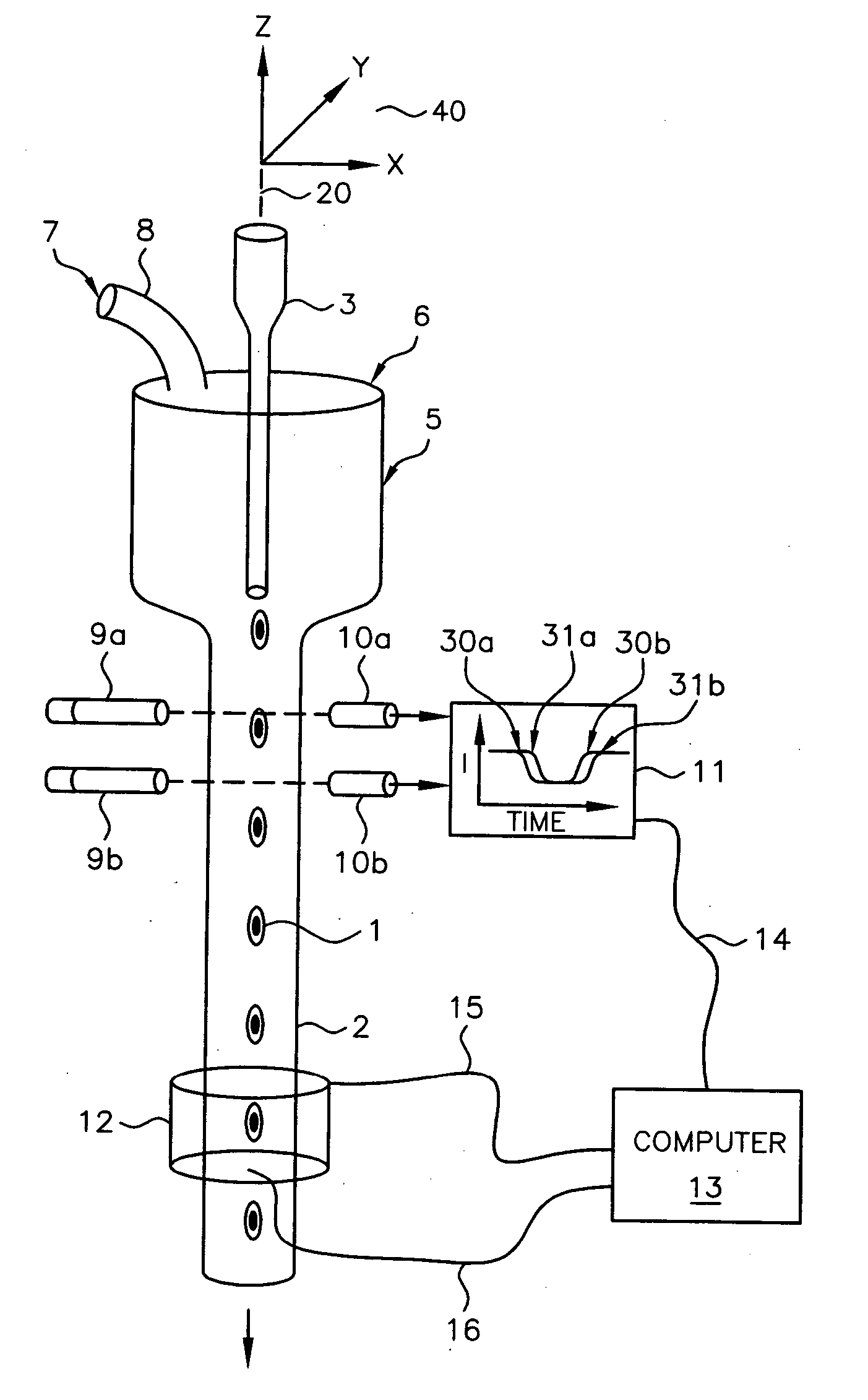
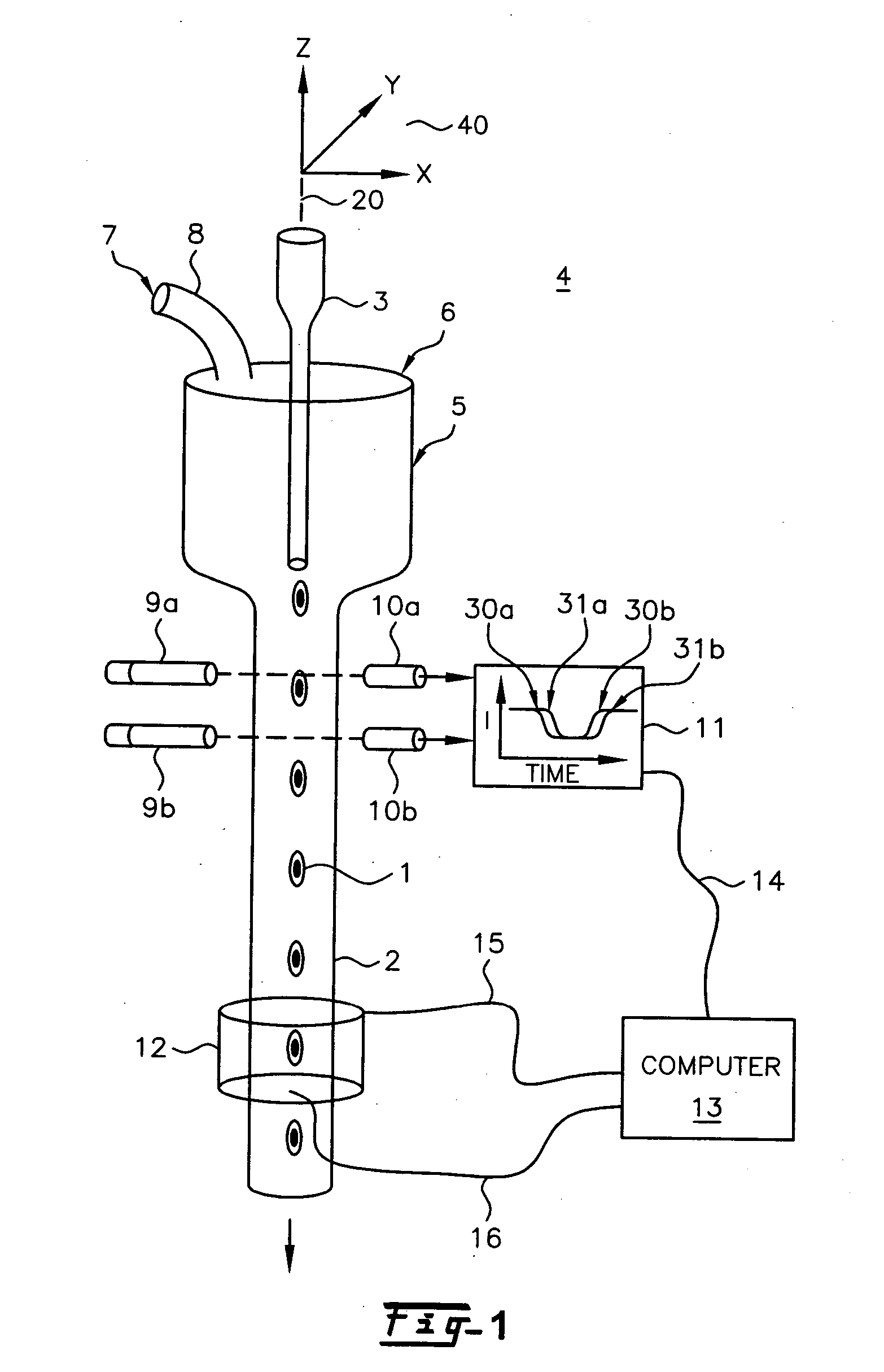
[0035] The invention is described herein with respect to specific examples relating to biological cells. It will be understood, however, that these examples are for the purpose of illustrating the principals of the invention, and that the invention is not so limited. In one example, constructing a three dimensional distribution of optical densities within a microscopic volume enables the quantification and the determination of the location of structures, molecules or molecular probes of interest. By using tagged molecular probes, the quantity of probes that attach to specific structures in the microscopic object may be measured. For illustrative purposes, an object such as a biological cell may be labeled with at least one stain or tagged molecular probe, and the measured amount and location of this probe may yield important information about the disease state of the cell, including, but not limited to, various cancers such as lung, breast, prostate, cervical and ovarian cancers.

[0...


PUM


Abstract

A shadowgram optical tomography system for imaging an object of interest. The shadowgram optical tomography system includes a parallel ray light source for illuminating the object of interest with a plurality of parallel radiation beams, an object containing tube, where the object of interest is held within the object containing tube such that it is illuminated by the plurality of parallel radiation beams to produce emerging radiation from the object containing tube, a detector array located to receive the emerging radiation, and a system and mehtod for tracking an image of the object of interest.

Description

RELATED APPLICATION [0001] This application claims priority from and is a continuation-in-part of co-pending and allowed U.S. application Ser. No. 10 / 308,309 of Johnson and Nelson, filed Dec. 3, 2002, entitled “OPTICAL TOMOGRAPHY OF SMALL OBJECTS USING PARALLEL RAY ILLUMINATION AND POST-SPECIMEN OPTICAL MAGNIFICATION,” that is in turn a continuation-in-part of U.S. Pat. No. 6,522,775 of Alan C. Nelson, issued Feb. 18, 2003, that is in turn related to the provisional application of Alan C. Nelson, Ser. No. 60 / 279,244, filed Mar. 28, 2001, both entitled “APPARATUS AND METHOD FOR IMAGING SMALL OBJECTS IN A FLOW STREAM USING OPTICAL TOMOGRAPHY.” U.S. application Ser. No. 10 / 308,309 of Johnson and Nelson, and U.S. Pat. No. 6,522,775 are hereby incorporated by reference in their entirety. [0002] This application is also related U.S. Pat. No. 6,591,003 issued Jul. 8, 2003 to Chu, entitled “OPTICAL TOMOGRAPHY OF SMALL MOVING OBJECTS USING TIME DELAY AND INTEGRATION IMAGING.”FIELD OF THE INV...

Claims


Application Information

Patent Timeline
IPC IPC(8): G01N21/00
CPCG01N15/147G01N21/4795G01N15/1475
Inventor MEYER, MICHAEL G.RAHN, JOHN RICHARDNELSON, ALAN C.JOHNSON, ROGER H.
Owner VISIONGATE
Why Eureka
Try Eureka