Goniophotometer

a goniophotometer and goniophotometer technology, applied in the field of goniophotometers, can solve the problems of unacceptably large change in the photometric characteristics of light sources, relatively difficult use of sphere photometers, and the inability to produce goniophotometers such as this with very major hardware complexity

a goniophotometer and goniophotometer technology, applied in the field of goniophotometers, can solve the problems of unacceptably large change in the photometric characteristics of light sources, relatively difficult use of sphere photometers, and the inability to produce goniophotometers such as this with very major hardware complexity

US20060023222A1Active Publication Date: 2006-02-02PATENT TREUHAND GESELLSCHAFT FUR ELECTRIC GLUEHLAMPEN MBH

Image

  • Goniophotometer
  • Goniophotometer
  • Goniophotometer

Examples


Embodiment Construction

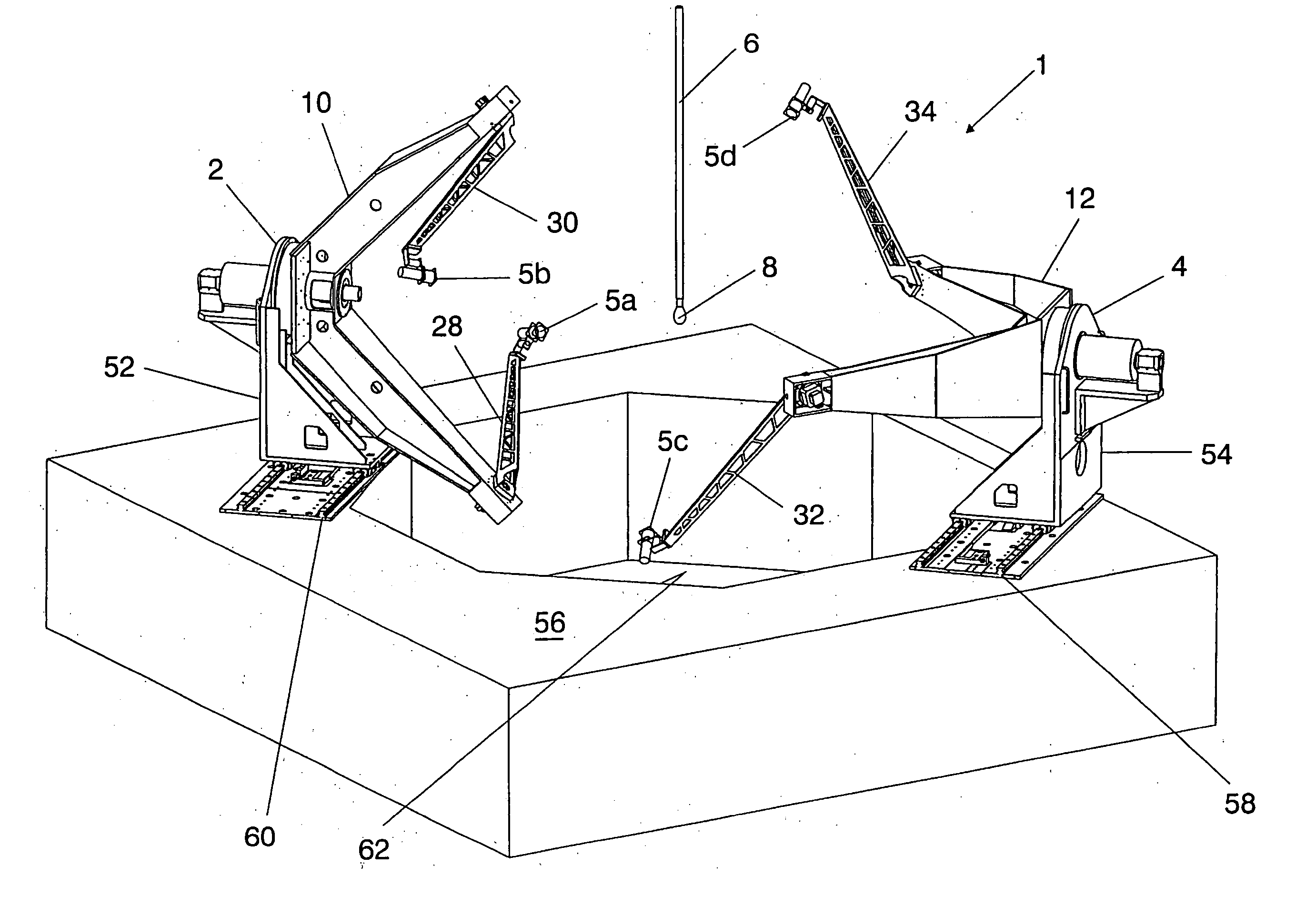
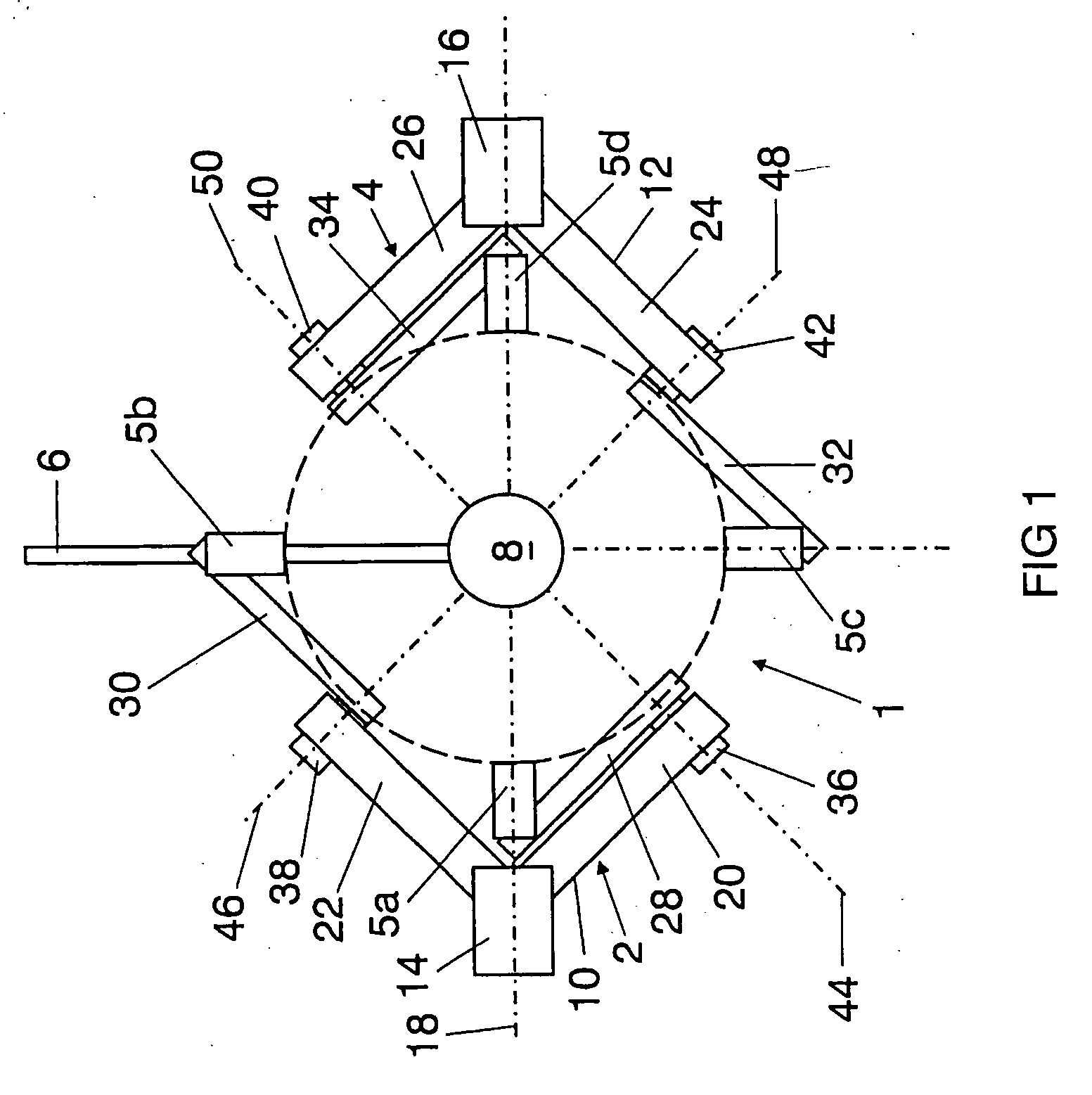
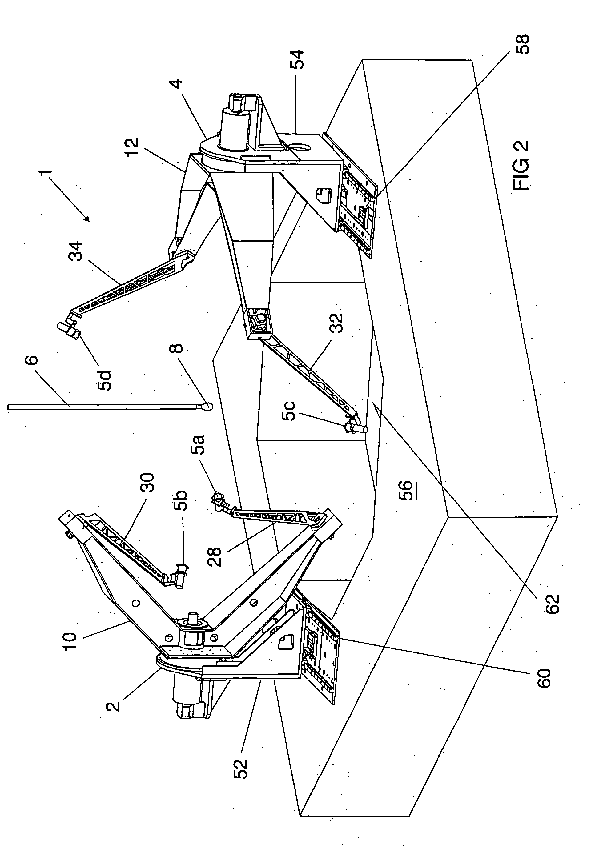
[0040]FIG. 1 shows a schematic illustration of a hemispherical goniophotometer 1 which essentially comprises two appliance units 2, 4 and a measurement object holder 6 which positions a light or radiation source, for example a lamp 8, between the two appliance units 2, 4.

[0041] Each appliance unit 2, 4 is fitted with two measurement heads 5a, 5b and 5c, 5d, respectively, with the kinematics being designed such that the two measurement heads 5a, 5b; 5c, 5d of the appliance units 2, 4 can each be moved along an envelope surface of a hemisphere. The hemispheres which are covered by the two appliance units 2, 4 are then added together to form a complete sphere, as is indicated by dashed lines in FIG. 1.

[0042] Each appliance unit 2, 4 has an approximately V-shaped respective rotating arm 10 or 12, which arms are in each case mounted by means of a main drive 14 or 16, respectively, such that they revolve around a common rotation axis 18 which runs through the lamp 8, which is held at it...


PUM

PropertyMeasurementUnit
angleaaaaaaaaaa
radiusaaaaaaaaaa
radiiaaaaaaaaaa

Abstract

A hemispherical goniophotometer is disclosed, in which two pivoting arms are articulated on a revolving rotating arm and are each fitted with a measurement head. The geometry of the arrangement is chosen such that the measurement heads can move along the envelope surface of a hemisphere during rotating of the rotating arm through 360Β° and pivoting of the pivoting arms through 180Β°.

Description

TECHNICAL FIELD [0001] The invention relates to a goniophotometer for measurement of photometric, spectroradiometric and / or colorimetric variables of the optic radiation from a light / radiation source which is held at a mounting position by a measurement object holder, having at least one measurement head which points at the light / radiation source and which, in order to record the variable, can be moved by means of a guide device, which is driven by a drive, along a predetermined movement path, preferably on an envelope surface of a sphere or hemisphere around the light / radiation source. BACKGROUND ART [0002] Either an Ulbricht sphere photometer or a goniophotometer is used in the normal manner in order to measure the light flux of a light / radiation source. [0003] The sphere photometer comprises a hollow sphere with an internal surface which is painted matt-white and produces multiply diffuse reflections of the light from a light source which is fitted in the interior, so that each a...

Claims


Application Information

Patent Timeline
02 Feb 2006
Publication
US20060023222A1
IPC
G01N21/47
CPC
G01J1/0242; G01J1/0403; G01J1/04
Inventors
BINDER, ULRICH; SAUTER, GEORG