Disk drive, positioning method for head, and servo system

a positioning method and disk drive technology, applied in the direction of track following on disks, magnetic recording, instruments, etc., can solve the problems of unstable servo system, virtually impossible to follow such a distance, and inability to read track servo signals, so as to improve system stability and efficiency. the effect of compensating for rro

Inactive Publication Date: 2006-02-02
HITACHI GLOBAL STORAGE TECH NETHERLANDS BV
View PDF1 Cites 2 Cited by
  • Summary
  • Abstract
  • Description
  • Claims
  • Application Information

AI Technical Summary

Benefits of technology

[0022] A third embodiment of the present invention is a method of head position control in a disk drive, intended to conduct position control of a head by use of the servo signals recorded on a recording disk. This method includes: accessing the recording disk having multiple tracks which each include an M number of servo sectors; reading servo signals associated with each servo sector; and, in accordance with three factors, (1) head position signals associated with the positions of the head that are determined from the servo signals of each servo sector, (2) a reference signal, and (3) a value based on the sum of the value obtained by multiplying, by a weighting coefficient, the multiple state variables that were input during movement of the head from the preset Nth previous sector to the current sector, and the output of the peak filter that is generated at the Mth previous sector, providing an output of a control signal for a driving device which moves the head; wherein, in a Nyquist diagram based on an open-loop transfer function of the servo system, when with regard to all polar “ωk”, except “ωk=0”, of the peak filter, Z0 is a point (−1, 0), Z01 is a point of the open-loop transfer function of the servo system at “ωk” in the case where the above-mentioned peak filter is not present, and Zk is a point of the open-loop transfer function of the servo system at “ωk” in the case where the above-mentioned peak filter is present, the Z0 point is present outside a curve extending from the neighborhood of the Z01 point through the Zk point toward the Z01 point. According to the present embodiment, a peak filter that efficiently compensates for RRO by using both the output value generated at the Mth previous sector, and the value obtained by multiplying the multiple state variables by the weighting coefficient, may be constructed in the disk drive. Also, the transfer function satisfies the above conditions and this enables system stability to be obtained. In terms of the ease in system stability design, it is preferable that the angle formed by a straight line extending from the Z0 point toward the Z01 point...

Problems solved by technology

The technology of Patent Document 2, however, does not enable track servo signals to be read if their recording pattern deviates from the round track significantly in terms of shape.
Therefore, it becomes virtually impossible for such a distance to be followed, which results in a position error.
The insertion of the peak filter, however, is most likely to make the servo system unstable.
If the system becomes unstable, the head cannot stay ...

Method used


Image

  • Disk drive, positioning method for head, and servo system
  • Disk drive, positioning method for head, and servo system
  • Disk drive, positioning method for head, and servo system

Examples


Embodiment Construction

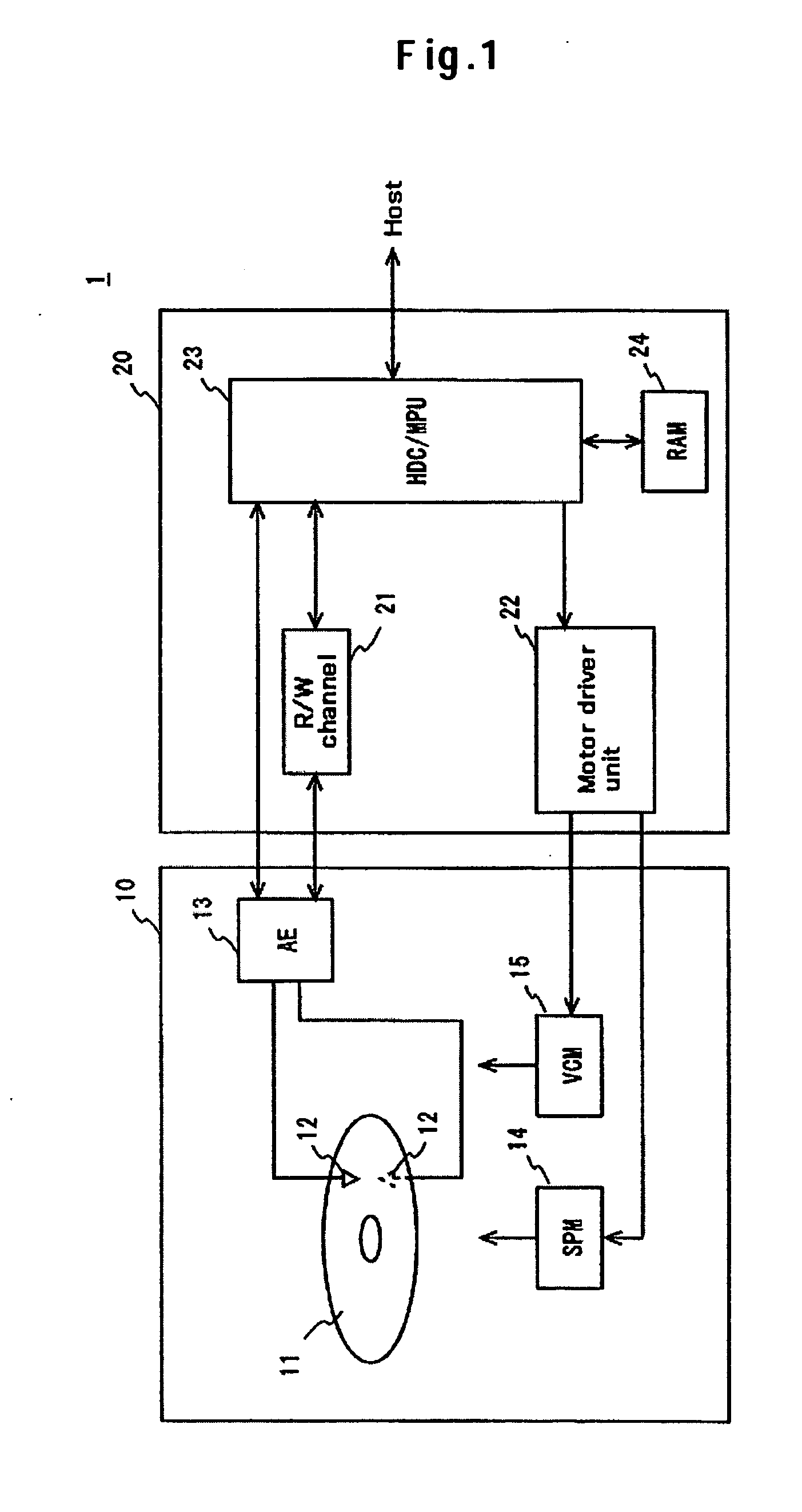
[0035] An embodiment that may be applied to the present invention is described below. The following description relates to an embodiment of the present invention, and the invention is not limited to / by the embodiment described below. For the brevity and clarity of description, the following description and drawings are omitted and simplified as appropriate. Also, that each element of the following embodiment may be easily modified, added, and transformed within the scope of the present invention will be understood by persons skilled in the art. In each drawing, the same reference numeral is assigned to the same element, and for the brevity and clarity of description, overlapped description is omitted as required.

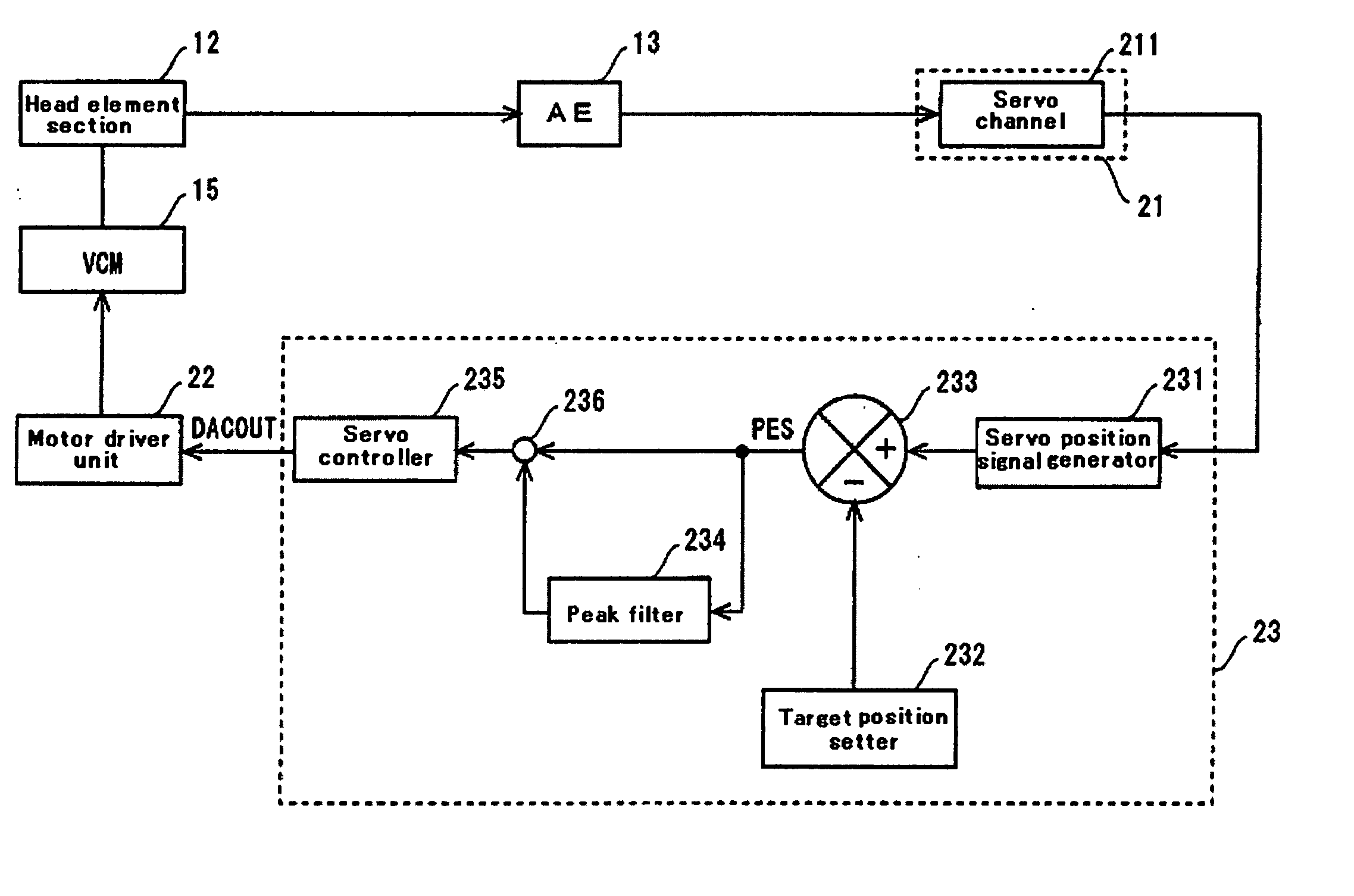
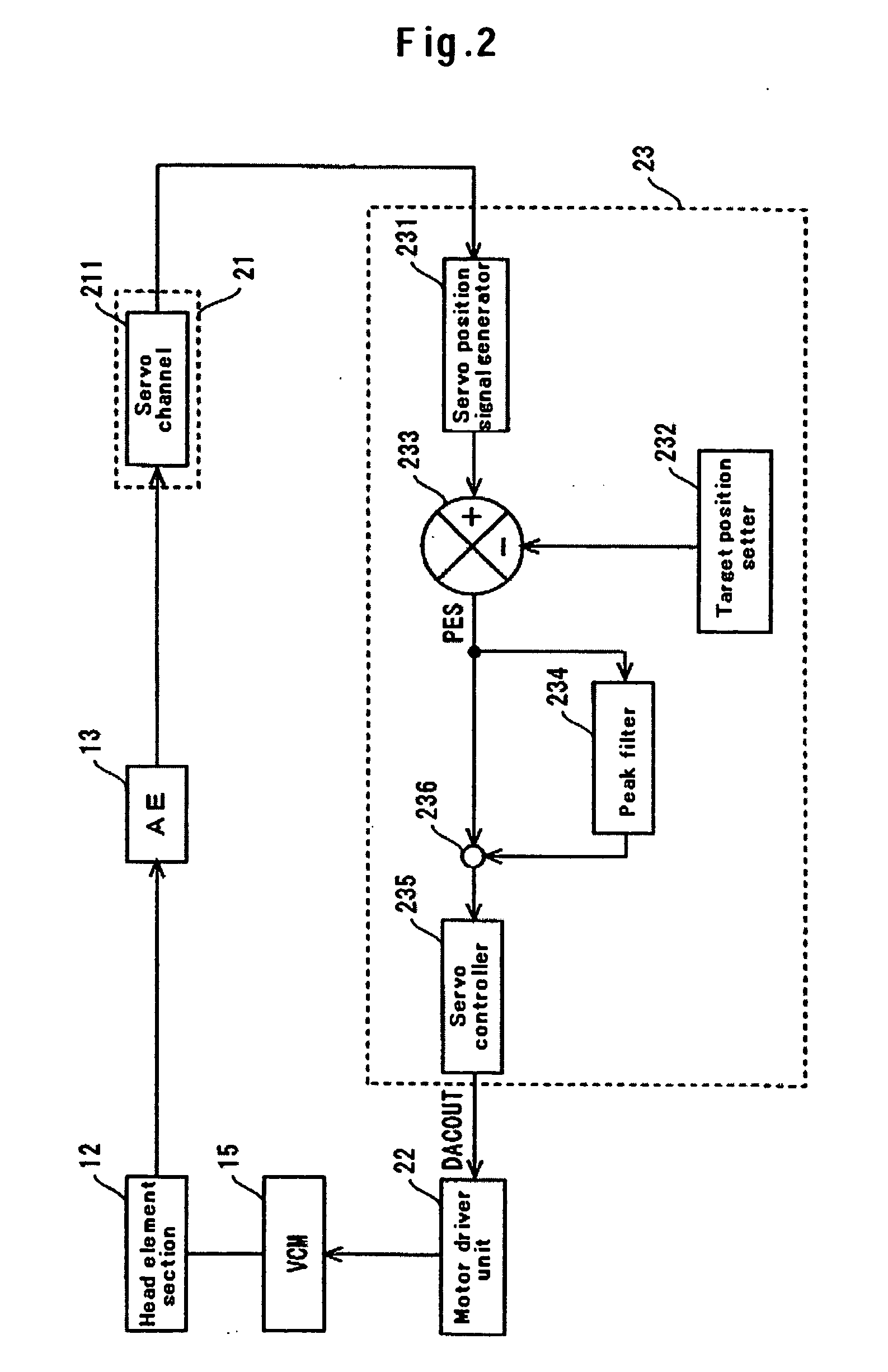
[0036] A hard-disk drive (HDD) of the present embodiment has a peak filter on a feedback route of a servo system. The peak filter is designed so that gains at a rotating speed of a magnetic disk and in the high-frequency components contained in the rotating speed take a def...


PUM


Abstract

Embodiments of the invention compensate for repeatable run-out errors without causing servo system instability. In one embodiment, HDD has a peak filter on a feedback route of a servo system. The peak filter is designed so that a rotating frequency of a magnetic disk, the high-frequency components contained in the rotating frequency and a peak match the rotating frequency and the high-frequency components. Insertion of a required peak filter into the servo system allows compensation for a repeatable run-out (RRO) error due to an event such as a deviation from the roundness of a track. Also, since a Nyquist diagram of the system satisfies required characteristics, a repeatable run-out error may be compensated for without causing instability of the servo system due to use of the peak filter.

Description

CROSS-REFERENCES TO RELATED APPLICATIONS [0001] This application claims priority from Japanese Patent Application No. JP2004-224749, filed Jul. 30, 2004, the entire disclosure of which is incorporated herein by reference. BACKGROUND OF THE INVENTION [0002] The present invention relates to a disk drive, a positioning method for a head, and a servo system. More particularly, the invention relates to a disk drive for compensating for repetition errors by means of a filtering process, and an associated head-positioning method and servo system. [0003] The devices that use various forms of media such as optical disks and magnetic tapes, are known as data storage devices. Among these devices, hard-disk drives (HDDs) have come into widespread use as storage devices in computers, and are one type of storage devices indispensable in current computer systems. In addition, HDDs are not only used in computers; the excellent characteristics of HDDs are increasingly expanding their applications su...

Claims


Application Information

Patent Timeline
IPC IPC(8): G11B5/596
CPCG11B5/59627
Inventor KISAKA, MASASHI
Owner HITACHI GLOBAL STORAGE TECH NETHERLANDS BV
Why Eureka
Try Eureka