Gas dynamic pressure bearing, motor having the gas dynamic pressure bearing, and disk drive having the motor

a technology of dynamic pressure bearing and gas dynamic pressure, which is applied in the direction of sliding contact bearings, mechanical equipment, mechanical energy handling, etc., can solve the problems that the material combination may not be optimized in terms of other aspects such as workability, price and lubricity, and achieve the effect of reducing the variation amount of radial gaps and allowing the expansion of the choice of members

Inactive Publication Date: 2006-02-02
NIPPON DENSAN CORP
View PDF9 Cites 5 Cited by
  • Summary
  • Abstract
  • Description
  • Claims
  • Application Information

AI Technical Summary

Benefits of technology

[0008] It is also possible to reduce the change of size of the gap which may be caused by a temperature change.
[0010] In this gas dynamic pressure bearing, when the temperature is 20° C., the sleeve is fitted to the hub and the sleeve is compressed toward the inner diameter side and fixed. If the temperature rises, the radial gap between the shaft and the sleeve tends to be narrow from the relation of α1<α0. This variation amount of the gap is defined as A. The fastening width between the sleeve and the hub is reduced from the relation of α1<α2 and thus, the surface pressure between the sleeve and the hub is moderated, and the sleeve tries to expand in radial direction. This expansion causes the radial gap between the shaft and the sleeve to be wide. The expansion amount is defined as B. As a result, the expansion amount B cancels the gap variation amount A each other, and the actual variation in radial gap caused by the temperature rises is reduced or suppressed. Further, since the above inequality is satisfied, the optimal material can be applied to various members in terms of workability, price and lubricity.
[0012] If the relation expression (1) is satisfied, the fastening width can be secured, in spite of the sleeve expanding in the using temperature range of the gas dynamic pressure bearing. In this case, however, if the thickness of the hub is excessively thin as compared with that of the sleeve, only the hub is deformed in the expansion direction when a shrinkage fitting or a press fitting is applied for fixing the hub, and a predetermined surface pressure is not applied to the sleeve. This is the reason why the relation expression (2) is set. With this, when the sleeve and the hub are fitted to each other with the fastening width which satisfies the relation expression (1), the predetermined surface pressure is applied therebetween. As a result, the variation of the radial gap is reduced and the looseness of the fitted portion is prevented.
[0022] According to the present invention, the variation amount of the radial gap is reduced only by setting the linear expansion coefficients of the members in the vicinity of the bearing surface to the predetermined inequality relations. Since the surface pressure of the fitted portions between the sleeve and the hub can be secured, the choice of the members can be widened. This is advantageous for various devices to which the gas dynamic pressure bearing is applied.

Problems solved by technology

Since the materials must be selected from such a range, the combination of the materials may not be optimized in terms of other aspects such as workability, price and lubricity.

Method used


Image

  • Gas dynamic pressure bearing, motor having the gas dynamic pressure bearing, and disk drive having the motor
  • Gas dynamic pressure bearing, motor having the gas dynamic pressure bearing, and disk drive having the motor
  • Gas dynamic pressure bearing, motor having the gas dynamic pressure bearing, and disk drive having the motor

Examples


Embodiment Construction

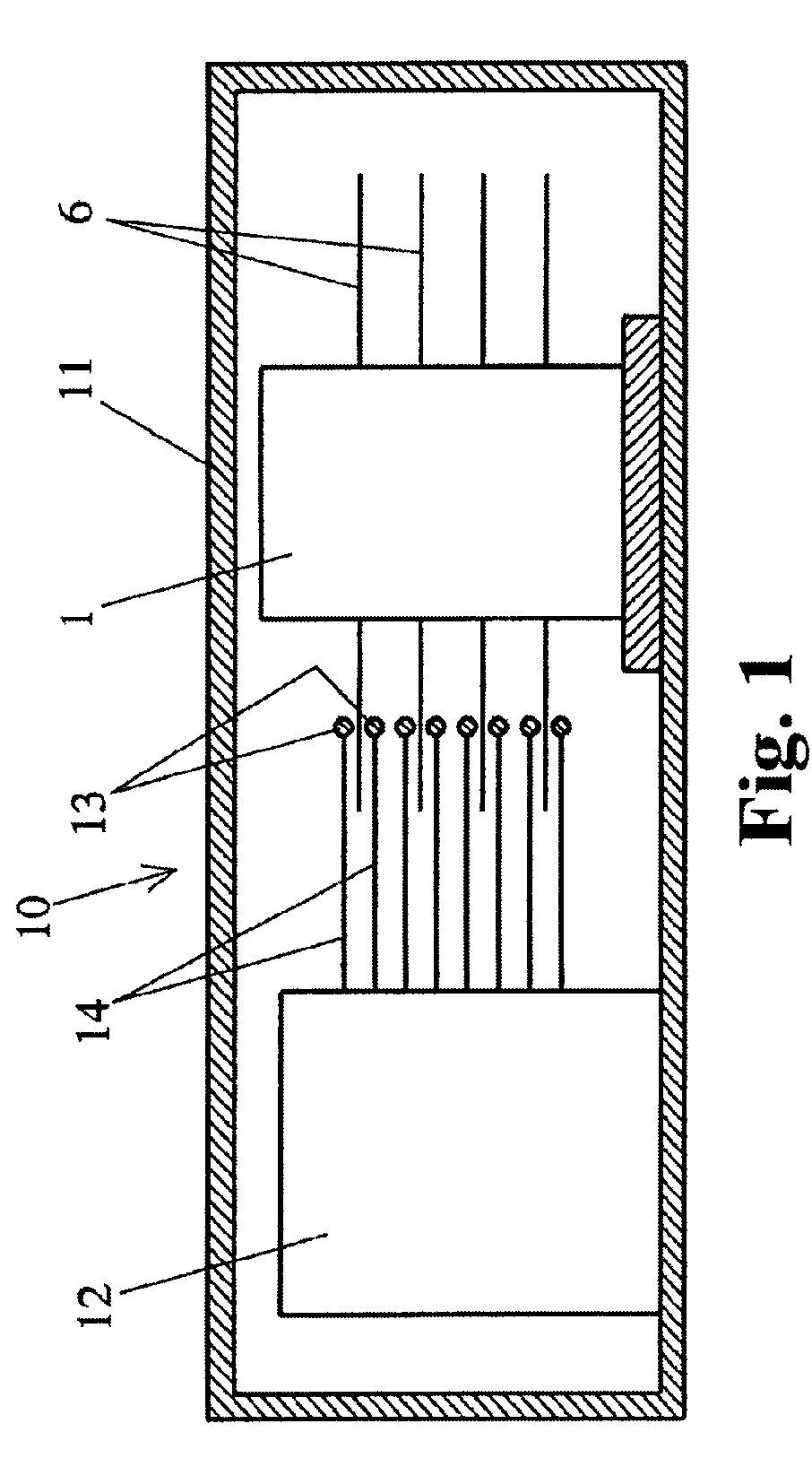
[0025] An embodiment of the present invention will be explained with reference to the drawings. FIG. 1 is a schematic sectional view of a hard disk drive according to an embodiment taken along an axial direction of rotation (axial direction, hereinafter). A hard disk drive 10 includes a housing 11 whose interior is kept clean, a dynamic pressure bearing motor (motor, hereinafter) 1 disposed in the housing 11, and an actuator 12. A plurality of (four in the drawing) magnetic disks 6 are mounted on the motor 1 in the axial direction. If the motor 1 is driven, the magnetic disks 6 rotate in a predetermined direction. Arms 14 having magnetic heads 13 are mounted on the actuator 12 with respect to the magnetic disks 6 such that the arms 14 extend in the radial direction. When the hard disk drive 10 is not used, the magnetic heads 13 are retreated together with the arms 14 to positions away from the magnetic disks 6, and if the motor 1 is driven, the magnetic heads 13 are turned by the op...


PUM


Abstract

A gas dynamic pressure bearing comprises a shaft, a sleeve whose inner peripheral surface is opposed to an outer peripheral surface of the shaft through a micro-gap, and a substantially cylindrical hub which applies a surface pressure to an outer side of the sleeve and which is fitted to the sleeve, and at least one of the outer peripheral surface of the shaft and the inner peripheral surface of the sleeve is formed with a dynamic pressure generating groove, and if linear expansion coefficients of the shaft, the sleeve and the hub are defined as a0, a1 and a2, respectively, a relation of a1<α0<α2 is satisfied.

Description

BACKGROUND OF INVENTION [0001] 1. Technical Field [0002] The present invention relates to a gas dynamic pressure bearing, a motor having the gas dynamic pressure bearing, and a disk drive having the motor. The present invention is utilized in a motor which rotates a magnetic disk such as a hard disk and a DVD, a disk apparatus and a laser printer having the motor. [0003] 2. Description of the Related Art [0004] A motor which rotates a magnetic disk such as a hard disk is required to rotate at high speed and with high precision. As bearing means of the motor which rotates the magnetic disk, a fluid dynamic pressure bearing capable of stably rotating is becoming pervasive. Generally, the fluid dynamic pressure bearing comprises two members, first and second members. The first member is a columnar shaft, and one or two disk-like thrust plates are disposed on one or both ends of the shaft. The second member is opposed to an outer peripheral surface of the shaft through a radial gap and ...

Claims


Application Information

Patent Timeline
IPC IPC(8): F16C32/06
CPCF16C17/107F16C41/008H02K7/086F16C33/107F16C33/1015
Inventor OKAYAMA, YOSHIKI
Owner NIPPON DENSAN CORP
Why Eureka
Try Eureka