Airfoil shape and sidewall flowpath surfaces for a turbine nozzle

Active Publication Date: 2006-02-02
IPSEN MFG IRELAND
View PDF7 Cites 27 Cited by
  • Summary
  • Abstract
  • Description
  • Claims
  • Application Information

AI Technical Summary

Benefits of technology

[0003] In accordance with the preferred embodiment of the present invention, there is provided unique nozzle flowpath surfaces, specifically an airfoil suction-side surface, an airfoil pressure side surface, an inner sidewall surface and an outer sidewall surface for the nozzle of a turbine stage,

Problems solved by technology

Conventional nozzle designs do not allow for the added benefit of advanced three-dimensional aerodynami

Method used


Image

  • Airfoil shape and sidewall flowpath surfaces for a turbine nozzle
  • Airfoil shape and sidewall flowpath surfaces for a turbine nozzle
  • Airfoil shape and sidewall flowpath surfaces for a turbine nozzle

Examples


Example

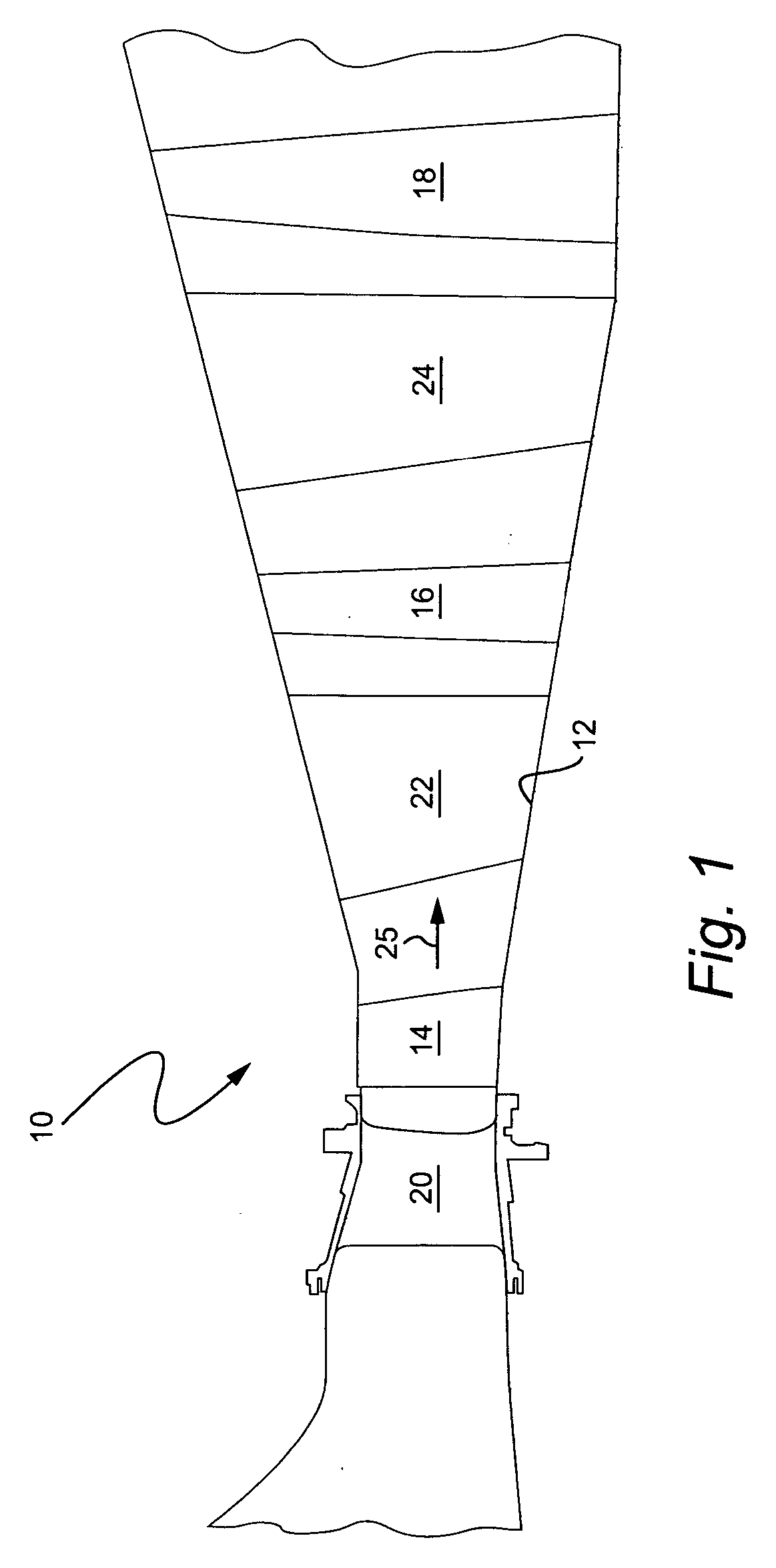
[0016] Referring now to FIG. 1, there is illustrated a portion of a turbine generally designated 10. Turbine 10 includes a rotor 12 mounting first, second and third stage buckets 14, 16 and 18 respectively. Stator vanes 20, 22 and 24 also form part of the respective first, second and third stages of the turbine. It will be appreciated that a three-stage turbine is accordingly illustrated having a gas flow path indicated by the arrow 24 in FIG. 1.

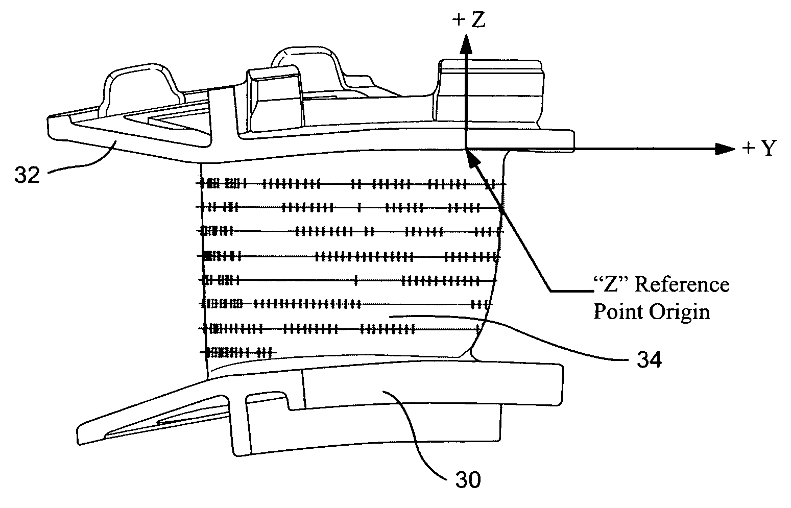
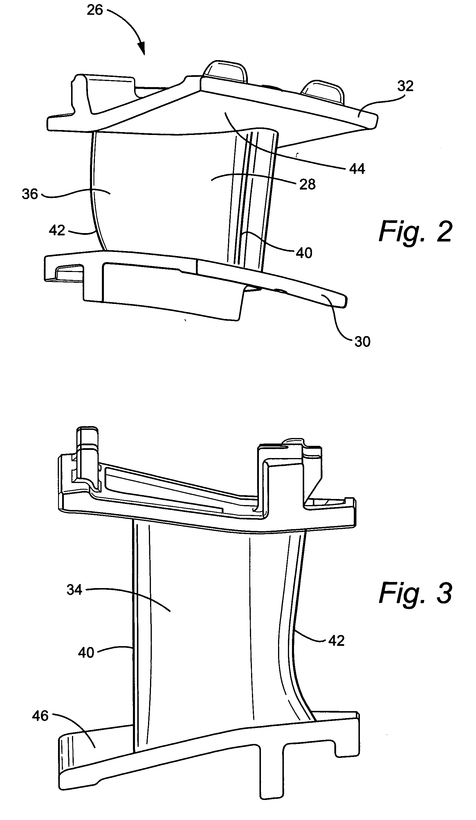
[0017] Referring to FIGS. 2-4, there is illustrated a nozzle stage segment generally designated 26 mounting an airfoil or vane 28 extending between inner and outer platforms or sidewalls 30 and 32 respectively. The nozzle segment 26 comprises one of a plurality of segments forming the first stage nozzle 20 and which segments 26 are disposed in a circumferential array thereof in the annular gas flow path 25. It will also be appreciated that each nozzle segment 26 may include one, two or more nozzle airfoils, e.g. vanes 28, extending between ...


PUM


Abstract

A turbine nozzle includes airfoil and sidewall surfaces. The airfoil and sidewall surfaces have profiles substantially in accordance with Cartesian coordinate values of X, Y and Z set forth in Tables I-IV for the pressure and suction sides of the airfoil, and the outer and inner sidewall surfaces, respectively. The X, Y and Z values are distances in inches. The X and Y values for the airfoil, when connected by smooth continuing arcs, define airfoil profile sections at each distance Z. The profile sections at the Z distances are joined smoothly with one another to form a complete airfoil shape. The X, Y and Z values of Tables III and IV define the outer and inner sidewall surfaces, respectively, of the gas flowpath.

Description

BACKGROUND OF THE INVENTION [0001] The present invention relates to a nozzle stage of a gas turbine and particularly relates to a first stage nozzle airfoil profile and sidewall flowpath surfaces. [0002] In the development of an advanced gas turbine, many specific requirements must be met for each stage of the hot gas path section of the turbine in order to meet design goals. Particularly, and in addition to other goals, the first stage of the turbine must meet efficiency, heat load, life, throat area and vectoring requirements to meet those goals. Conventional nozzle designs do not allow for the added benefit of advanced three-dimensional aerodynamics that improve the use of the combustion gases to improve blade loading sufficiently to meet that goal. BRIEF DESCRIPTION OF THE INVENTION [0003] In accordance with the preferred embodiment of the present invention, there is provided unique nozzle flowpath surfaces, specifically an airfoil suction-side surface, an airfoil pressure side ...

Claims


Application Information

Patent Timeline
IPC IPC(8): F01D1/02
CPCF01D5/141F05D2250/70F05D2250/74
Inventor PHILLIPS, JAMES STEWARTWEDLAKE, RAYMOND ALLANGILL, RANDALL DOUGLAS
Owner IPSEN MFG IRELAND
Why Eureka
Try Eureka