Electric pump and modularized fuel supply system with such electric pump

Inactive Publication Date: 2006-02-02
AISAN IND CO LTD
View PDF9 Cites 35 Cited by
  • Summary
  • Abstract
  • Description
  • Claims
  • Application Information

AI Technical Summary

Benefits of technology

[0041] According to another embodiment of the modularized fuel supply system, the front-end filter is provided with an outlet path. The outlet path is connected with the outlet port (first outlet port) discharging the fuel, which is drawn into the pump section of the fuel pump, directly to the outside of the pump. The fuel discharged from the outlet port flows into a predetermined part through the outlet path. Thus, a dedicated component forming the outlet path is not required. This makes it possible to make the fuel supply system compact and lightweight, and reduce the manufacturing cost.
[0042] According to another embodiment of the modularized fuel supply system, the inlet port of the fuel pump is connected with the inlet path exit of the front-end filter in a fitting structure with a male port and a corresponding female port. This allows the connecting operation between the inlet port of the fuel pump and the inlet path exit of the front-end filter to be easily performed.
[0043] According to another embodiment of the modularized fuel supply system, a sealing member is interposed between the inlet port of the fuel pump and the inlet path exit of the front-end filter. This reduces or prevents fuel leakages from a connecting portion between the inlet port of the fuel pump and the inlet path exit of the front-end filter.
[0044]

Problems solved by technology

It is to be noted that the vapor cannot be effectively vented at a point located before the quarter of the pumping

Method used


Image

  • Electric pump and modularized fuel supply system with such electric pump
  • Electric pump and modularized fuel supply system with such electric pump
  • Electric pump and modularized fuel supply system with such electric pump

Examples


first representative embodiment

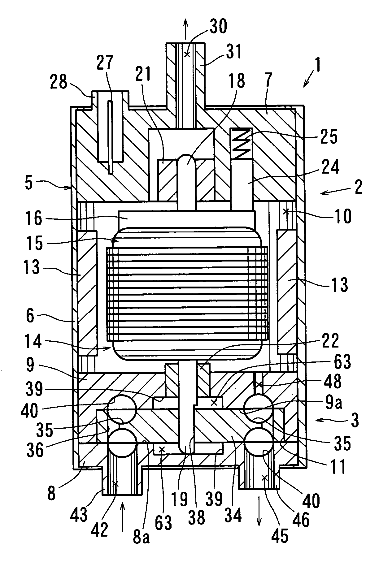
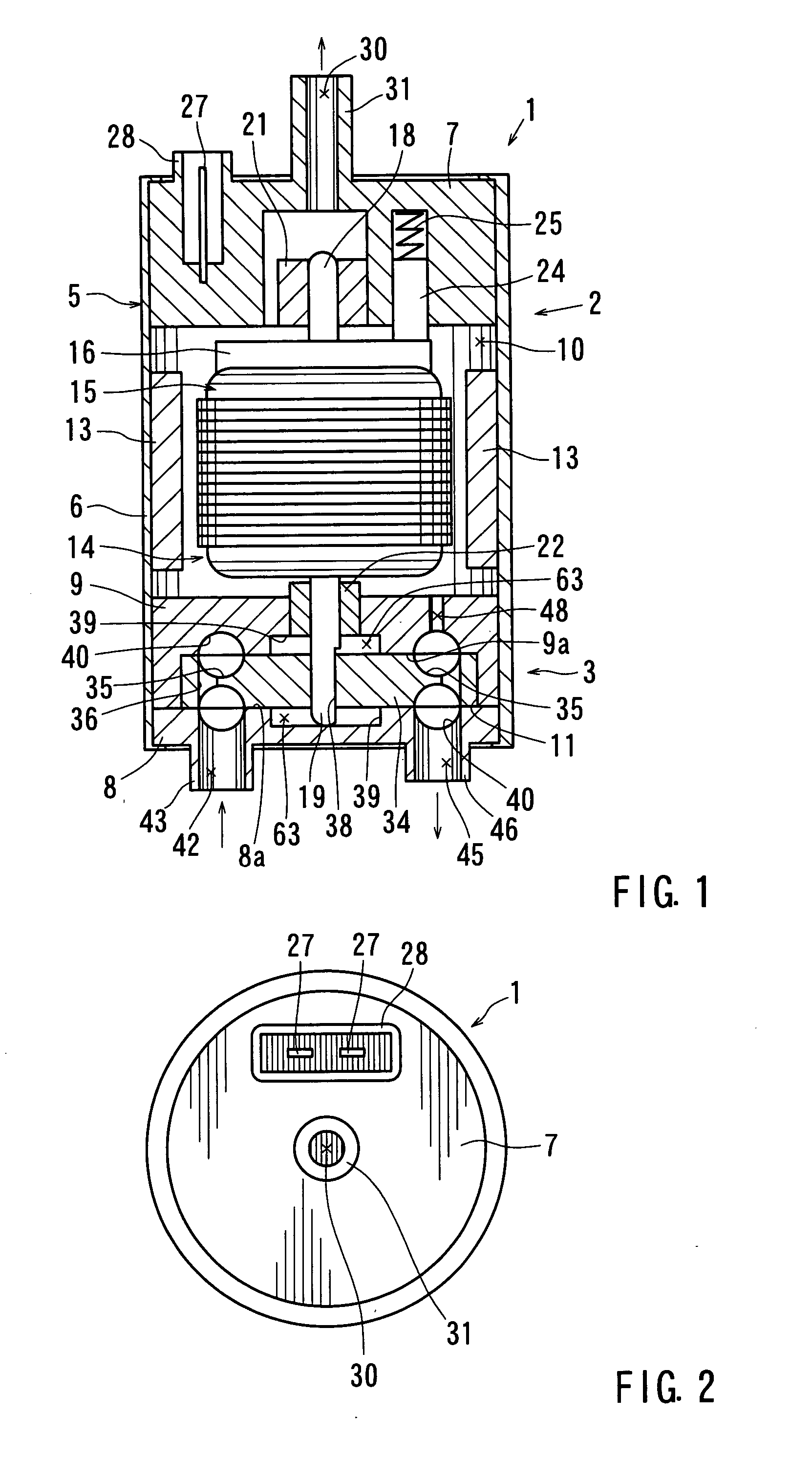
[0081] Turning now to the drawings, a fuel pump according to a first representative embodiment (hereinafter referred to as a “first representative fuel pump”) is shown in FIGS. 1 to 7.

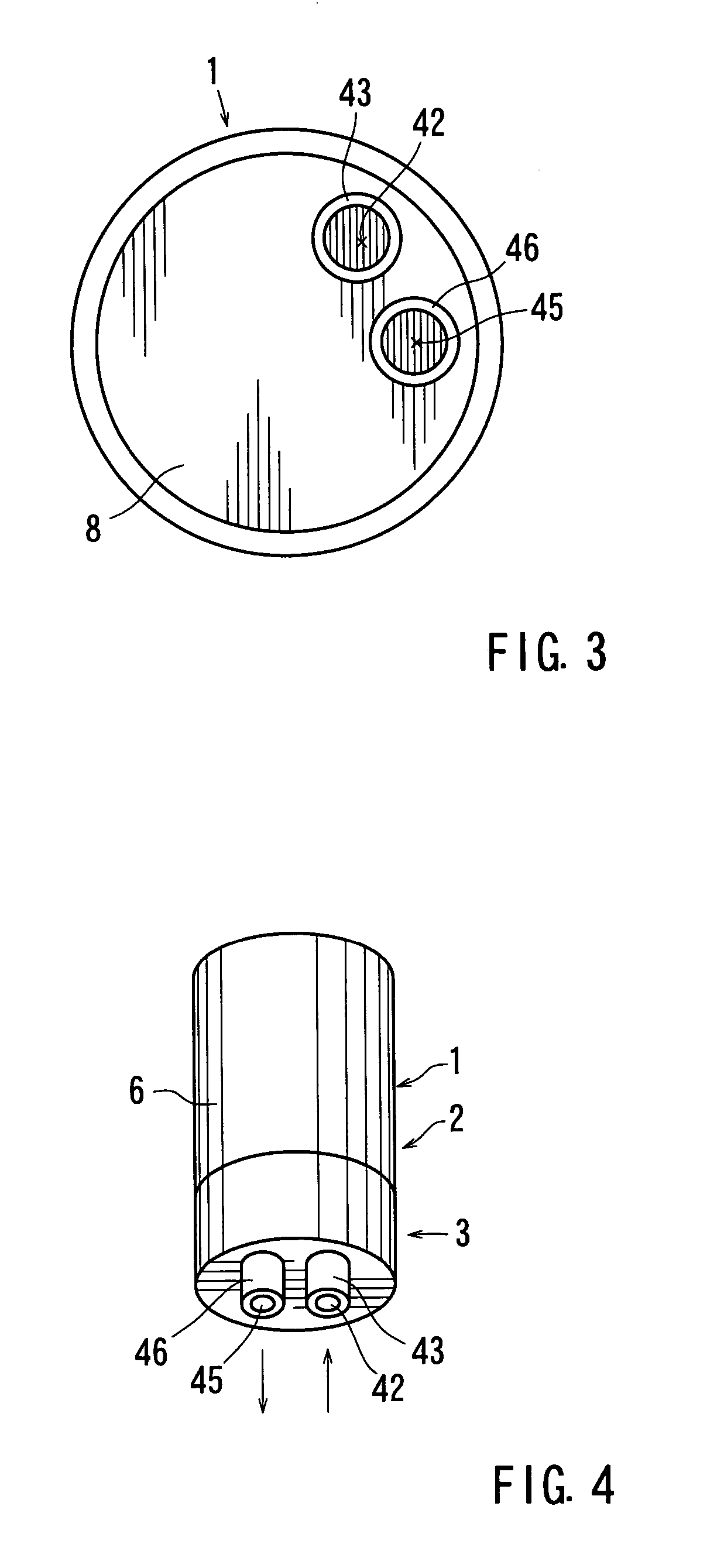
[0082] Referring to FIG. 1, a fuel pump 1 is integrally provided with a motor section 2 and a pump section 3. The pump section 3 is disposed at one end of the motor section 2 (the lower end in FIG. 1). The outer shell of the fuel pump 1 is a pump casing 5, which includes a generally tubular shell 6, a motor cover 7 sealing one end of the tubular shell (the upper end in FIG. 1), a pump cover 8 sealing the other end of the tubular shell (the lower end in FIG. 1), and a pump housing 9 overlayingly provided on the pump cover 8 to partition the inside area of the pump casing 5 into a motor compartment 10 and a pump compartment 11. It is to be noted that the motor cover 7 is also referred to herein as an “end cap member of the motor section.” Similarly, the pump cover 8 is also referred to herein as an “end...

second representative embodiment

[0097] Referring to FIG. 8, a fuel pump according to a second representative embodiment (hereinafter referred to as a “second representative fuel pump”) will be described. Since the second representative fuel pump is a modification of the first representative fuel pump, the description will be made only for the features that are different from the first representative fuel pump. As shown in FIG. 8, the second representative fuel pump 1 is modified in the shaft structure of the pump side of the armature 14 and the connection structure between the armature 14 and the impeller 34. As clearly understood when comparing with FIG. 5 of the first representative fuel pump 1, the pump side or the lower end of the shaft 18 has a generally round-bar-shaped shaft portion 18a, without a connecting portion 19 (see FIG. 5). The lower shaft portion 18a of the shaft 18 is rotatably supported by a bearing 50, which is mounted in the supporting hole 49 formed on the bottom surface of the pump cover rec...

third representative embodiment

[0108] Referring to FIGS. 9 and 10, a fuel pump according to a third representative embodiment (hereinafter referred to as a “third representative pump”) will be described. The third representative fuel pump is a modification of the first representative fuel pump. As shown in FIG. 9, the third representative fuel pump 1 is modified in that the second outlet port 30, defined by the second outlet tube 31 of the motor cover 7 of the first representative fuel pump 1, is provided with a check valve or a ball member 67. The lower portion of the second outlet port 30 within the second outlet tube 31 is provided with a valve seat 68, which is closed or opened by the ball member 67. On the other hand, the upper portion of the second outlet port 30 within the second outlet tube 31 is provided with a ball stopper 69, for example, formed in a C-shaped ring. The ball stopper 69 prevents the ball member 67 from ejecting out of the second outlet tube 31. When a fuel flows from the motor compartmen...


PUM


Abstract

An electric pump (1) comprises a pump section (3) drawing a fluid into the pump compartment (11), a motor section (2) including a rotatable armature (14) in the motor compartment (10) driving the pump section (3). The pump (1) also comprises an outlet port (45) allowing a drawn and pressurized fluid to be discharged to the outside of the pump (1), and a communicating opening (48) discharging a portion of the fuel from the pump section (3) into the motor compartment (10). The fluid from the pump compartment (11) is discharged directly from the outlet port (45), not through the motor compartment (10). The portion of the fluid from the pump section (3) flows into the motor compartment (10) via the communicating opening (48), and is finally discharged from the second outlet port (30) after passing through the motor compartment (10).

Description

[0001] This application claims priority to Japanese patent application serial number 2004-220108, the contents of which are incorporated herein by reference. BACKGROUND OF THE INVENTION [0002] 1. Field of the Invention [0003] The present invention relates to an electric pump used, for example, as an in-tank fuel pump for a pumping fuel stored in a automobile fuel tank, and a modularized fuel supply system with such an electric pump. [0004] 2. Description of the Related Art [0005] Referring now to FIG. 30, the prior art fuel pump utilizing an electric pump will be described. This type of fuel pump is known as a turbine-type or impeller-type pump. The fuel pump 201 integrally includes a motor section 202 and a pump section 203 provided at one end of the motor section (at the lower end in FIG. 30). The outer shell of the fuel pump 201 is a pump casing 205, which includes a generally tubular shell 206, a motor cover 207 sealing one end of the tubular shell (the upper end in FIG. 30), a ...

Claims


Application Information

Patent Timeline
IPC IPC(8): F04B39/06F04B17/00
CPCF02M37/048F04D13/06F04D5/002F04D9/003F04D29/5806F02M37/08F02M69/00
Inventor IKEYA, MASAKI
Owner AISAN IND CO LTD
Why Eureka
Try Eureka