
Methods of forming a multi-bridge-channel MOSFET

a technology of metal oxide semiconductor and field effect transistor, which is applied in the direction of semiconductor devices, basic electric elements, electrical appliances, etc., can solve the problems of affecting the characteristics of the transistor, unable to obtain a sufficient effective channel length or effective channel width of the transistor, and increasing the threshold voltag

Active Publication Date: 2006-02-02
SAMSUNG ELECTRONICS CO LTD
View PDF12 Cites 64 Cited by
  • Summary
  • Abstract
  • Description
  • Claims
  • Application Information

AI Technical Summary

Problems solved by technology

The downscaling of the active region may preclude obtaining a sufficient effective channel length or effective channel width of a transistor.
A reduction in the channel length of a transistor, such as a metal oxide semiconductor field effect transistor (MOSFET), may make a short channel effect predominant, thus adversely affecting the characteristics of the transistor.
Also, as the channel width of a transistor decreases, a narrow width effect, which results in an increase of threshold voltage, may become more prominent and have a bad influence on the transistor.
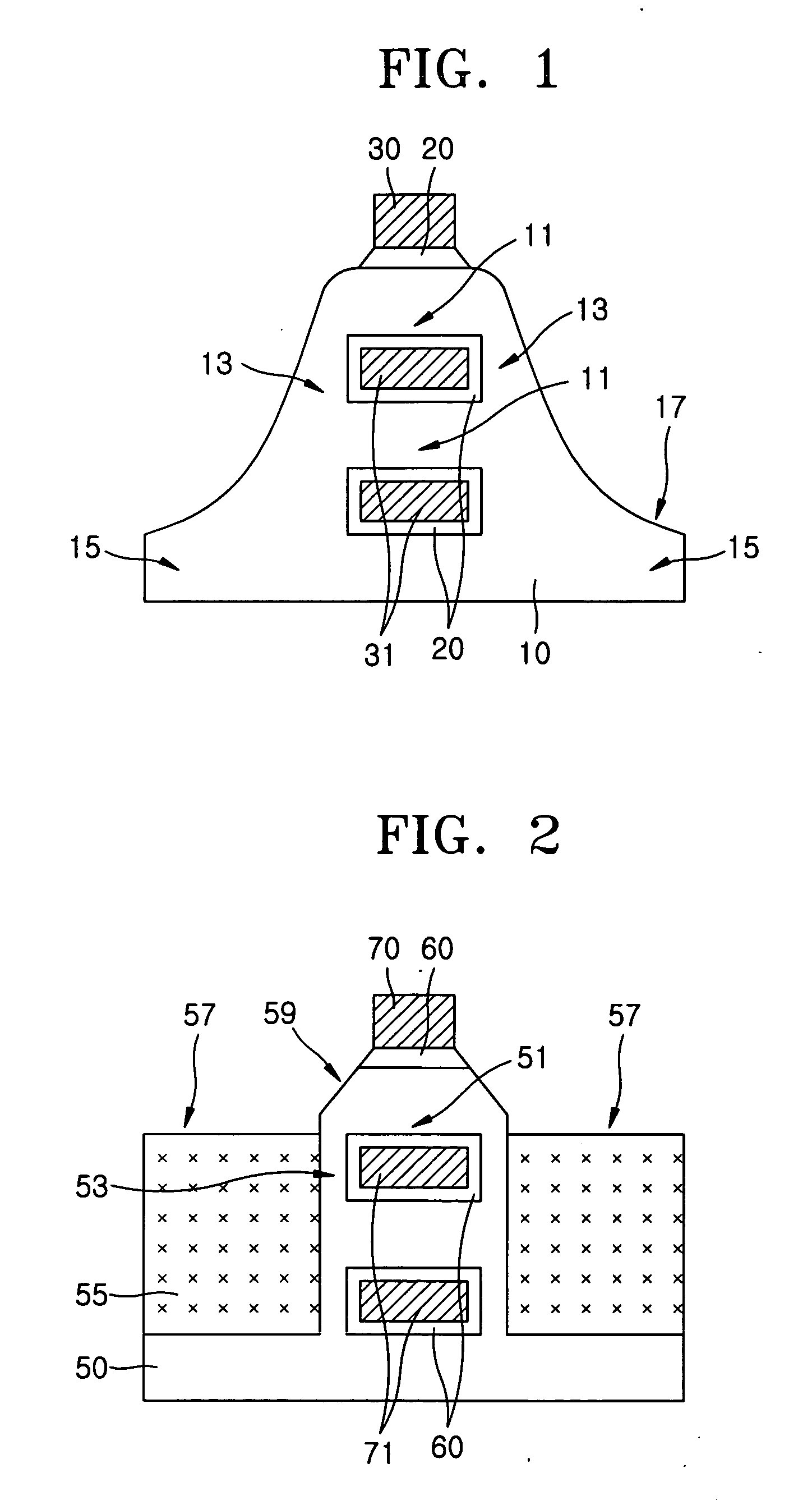
A typical MBCFET has the above-described structure, but a process of manufacturing the MBCFET may include some problems.
In this case, the buried oxide layer or the BOX may be exposed because an over etch margin is insufficient in an etch process for forming a path required for forming the branch layers 31.
Accordingly, it may become difficult to form the source and drain regions 15.
Moreover, owing to the step difference between the source and drain regions 15 and the top layer of the gate 30, it may be difficult to perform a subsequent metallization, which is required to selectively form a metal electrode layer at the contact position 17 on the source and drain regions 15.
However, the foregoing structure assists in reducing the step difference, but makes a manufacturing process complicated because the manufacturing process involves depositing and etching back a polysilicon layer.
Further, by etching the corners of the channel 51, an etchback margin may be insufficient.

Method used


Image

  • Methods of forming a multi-bridge-channel MOSFET
  • Methods of forming a multi-bridge-channel MOSFET
  • Methods of forming a multi-bridge-channel MOSFET

Examples


Embodiment Construction

[0055] The invention now will be described more fully hereinafter with reference to the accompanying drawings, in which embodiments of the invention are shown. This invention may, however, be embodied in many different forms and should not be construed as limited to the embodiments set forth herein. Rather, these embodiments are provided so that this disclosure will be thorough and complete, and will fully convey the scope of the invention to those skilled in the art. Like reference numerals refer to like elements throughout the description of the figures.

[0056] It will be understood that when an element is referred to as being “on” another element, it can be directly on the other element or intervening elements may be present. In contrast, when an element is referred to as being “directly on” another element, there are no intervening elements present. As used herein, the term “and / or” includes any and all combinations of one or more of the associated listed items.

[0057] It will b...


PUM


Abstract

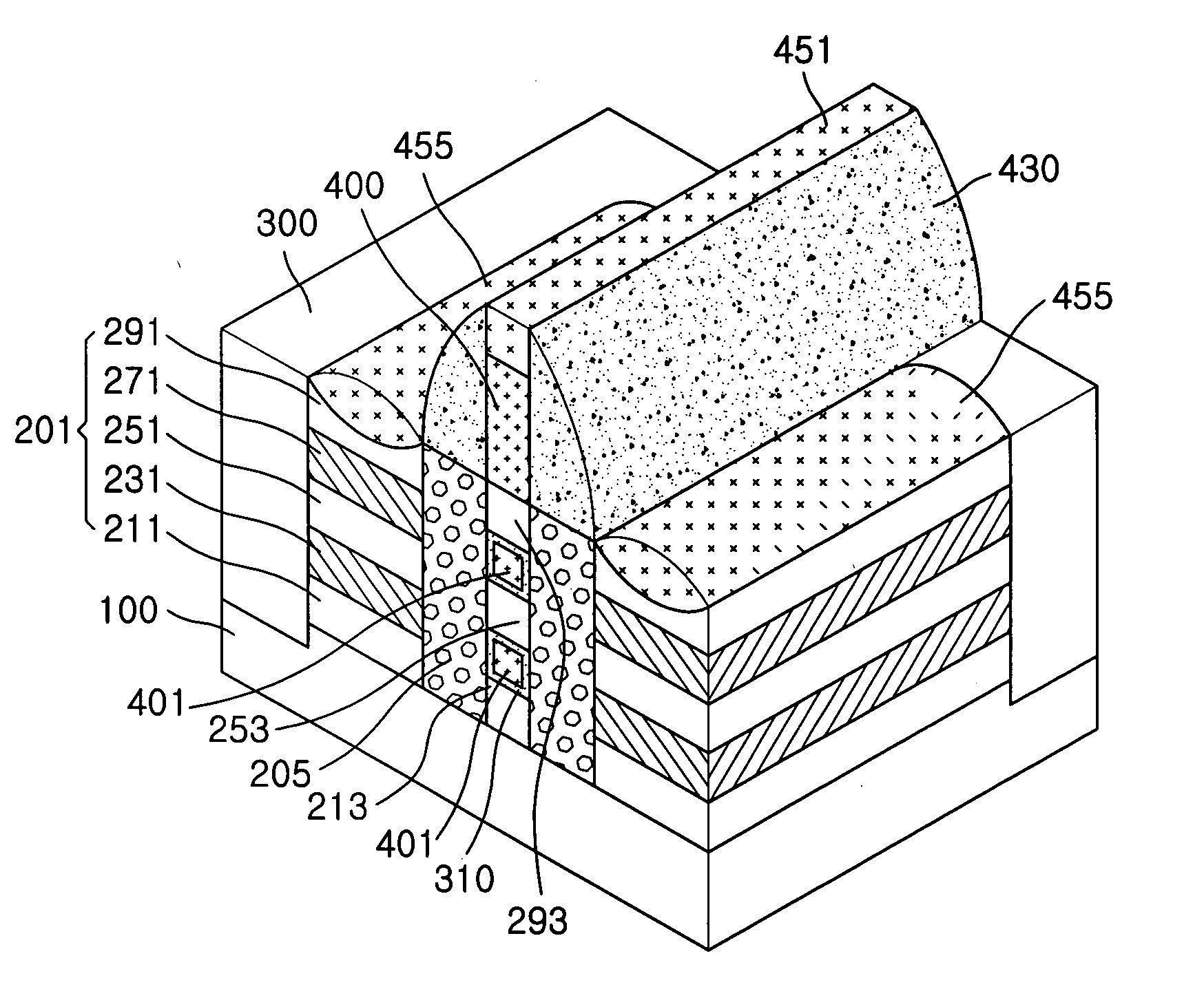
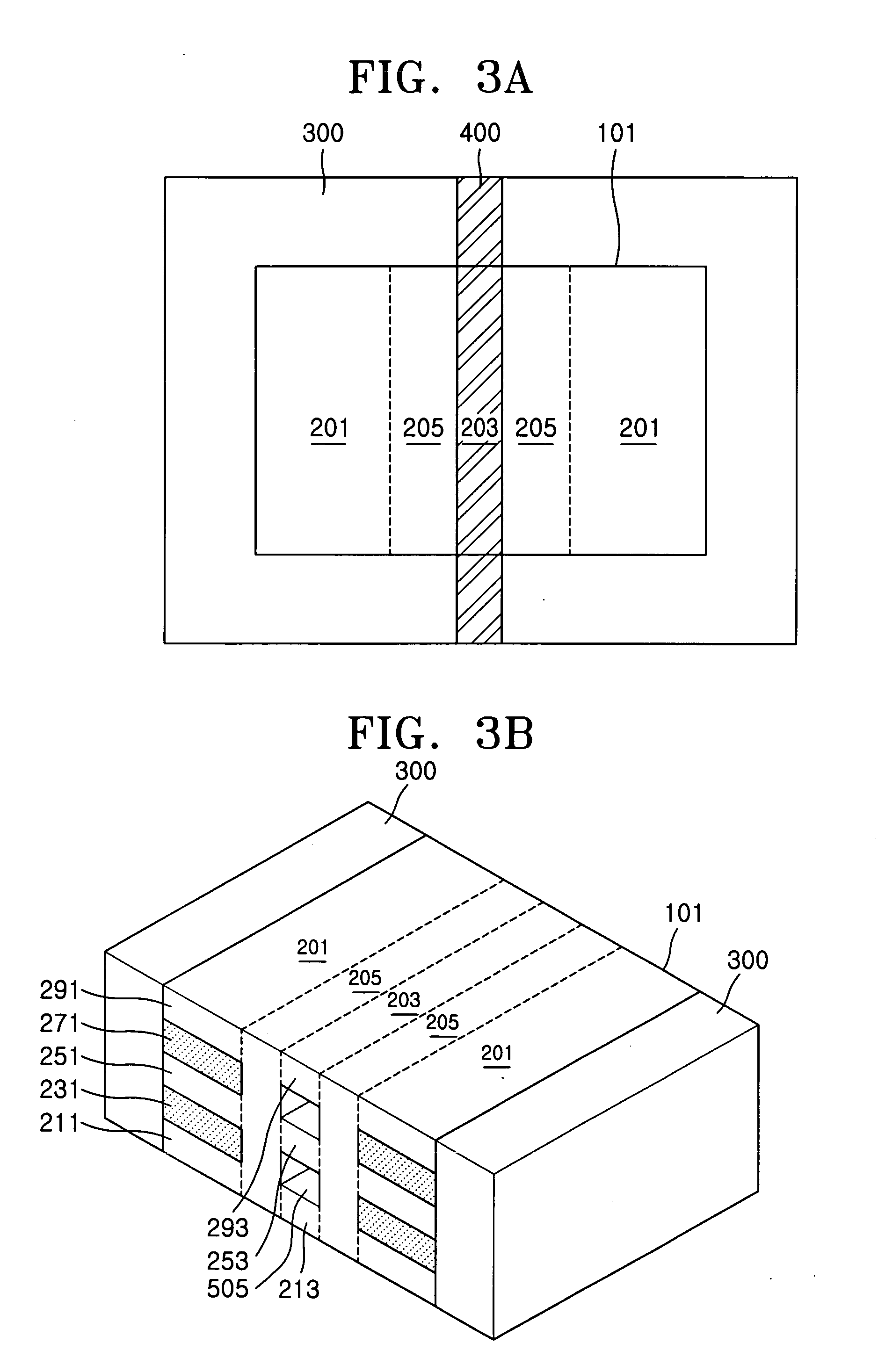
A multi-bridge-channel MOSFET (MBCFET) may be formed by forming a stacked structure on a substrate that includes channel layers and interchannel layers interposed between the channel layers. Trenches are formed by selectively etching the stacked structure. The trenches run across the stacked structure parallel to each other and separate a first stacked portion including channel patterns and interchannel patterns from second stacked portions including channel and interchannel layers remaining on both sides of the first stacked portion. First source and drain regions are grown using selective epitaxial growth. The first source and drain regions fill the trenches and connect to second source and drain regions defined by the second stacked portions. Marginal sections of the interchannel patterns of the first stacked portion are selectively exposed. Through tunnels are formed by selectively removing the interchannel patterns of the first stacked portion beginning with the exposed marginal sections. The through tunnels are surrounded by the first source and drain regions and the channel patterns. A gate is formed along with a gate dielectric layer, the gate filling the through tunnels and extending onto the first stacked portion.

Description

CROSS REFERENCE TO RELATED APPLICATION [0001] This application claims the priority of Korean Patent Application No. 2004-60101, filed on Jul. 30, 2004, in the Korean Intellectual Property Office, the disclosure of which is hereby incorporated herein by reference in its entirety. BACKGROUND OF THE INVENTION [0002] 1. Field of the Invention [0003] The present invention relates to methods of forming semiconductor devices, and, more particularly, to methods of forming a multi-bridge-channel metal oxide semiconductor field effect transistor (MBCFET). [0004] 2. Description of the Related Art [0005] As the integration density of semiconductor memory devices has increased, the area of an active region where elements are disposed has gradually been scaled down. The downscaling of the active region may preclude obtaining a sufficient effective channel length or effective channel width of a transistor. [0006] A reduction in the channel length of a transistor, such as a metal oxide semiconducto...

Claims


Application Information

Patent Timeline
Patent Type & Authority Applications(United States)
IPC IPC(8): H01L21/336
CPCH01L29/42392H01L29/78696H01L29/66772H01L29/41725
Inventor YUN, EUN-JUNGKIM, SUNG-MINLEE, SUNG-YOUNG
Owner SAMSUNG ELECTRONICS CO LTD
Learn More