
Radio information communicating system

a technology of information communication and communication system, applied in the field of radio information communication system, can solve the problems of dcf, high possibility of abandoning audio packet in an unsent state within the system, and high probability of dcf, so as to reduce the load of control

Inactive Publication Date: 2006-02-02
PANASONIC CORP
View PDF3 Cites 14 Cited by
  • Summary
  • Abstract
  • Description
  • Claims
  • Application Information

AI Technical Summary

Benefits of technology

[0006] As a method for solving the above-mentioned problem, PCF (Point Coordination Function) using polling by a radio base station may be conceivable. PCF is a communication method in which a radio base station sequentially grants each radio terminal a transmission right and the radio terminal having obtained the transmission right performs a transmission of a packet. Thus, the radio terminal having obtained a transmission right can periodically transmit packets of data to be transmitted. As a result, abandonment of an audio packet due to the above-mentioned time-out is less likely to occur.
[0008] Therefore, an object of the present invention is to provide a wireless LAN system which can be controlled, without a heavy load on the whole system, in such a manner that specific data such as audio data will not be abandoned within a radio terminal at the transmitting end due to time-out.
[0010] According to the above-mentioned radio information communicating system, an AP does not need to perform polling constantly. As a result, the control load on the AP is reduced. Moreover, because a radio terminal is compulsorily granted a transmission right through polling, abandonment of a packet due to time-out is prevented.

Problems solved by technology

However, while allowing for light control, the aforementioned DCF has a problem described below.
Here, under the aforementioned DCF, because of the occurrence of collisions between packets and a back-off process, a delay in a packet transmission is prone to happen.
Consequently, the aforementioned DCF has a problem in that there is a high possibility of abandoning the audio packet in an unsent state within the system.
Nevertheless, the aforementioned PCF has problems in that, since a radio base station must manage and control all radio terminals, there is a heavy control load, and that because polling is periodically performed even to a radio terminal generating packets in burst fashion, it is ineffective.

Method used


Image

  • Radio information communicating system
  • Radio information communicating system
  • Radio information communicating system

Examples


Embodiment Construction

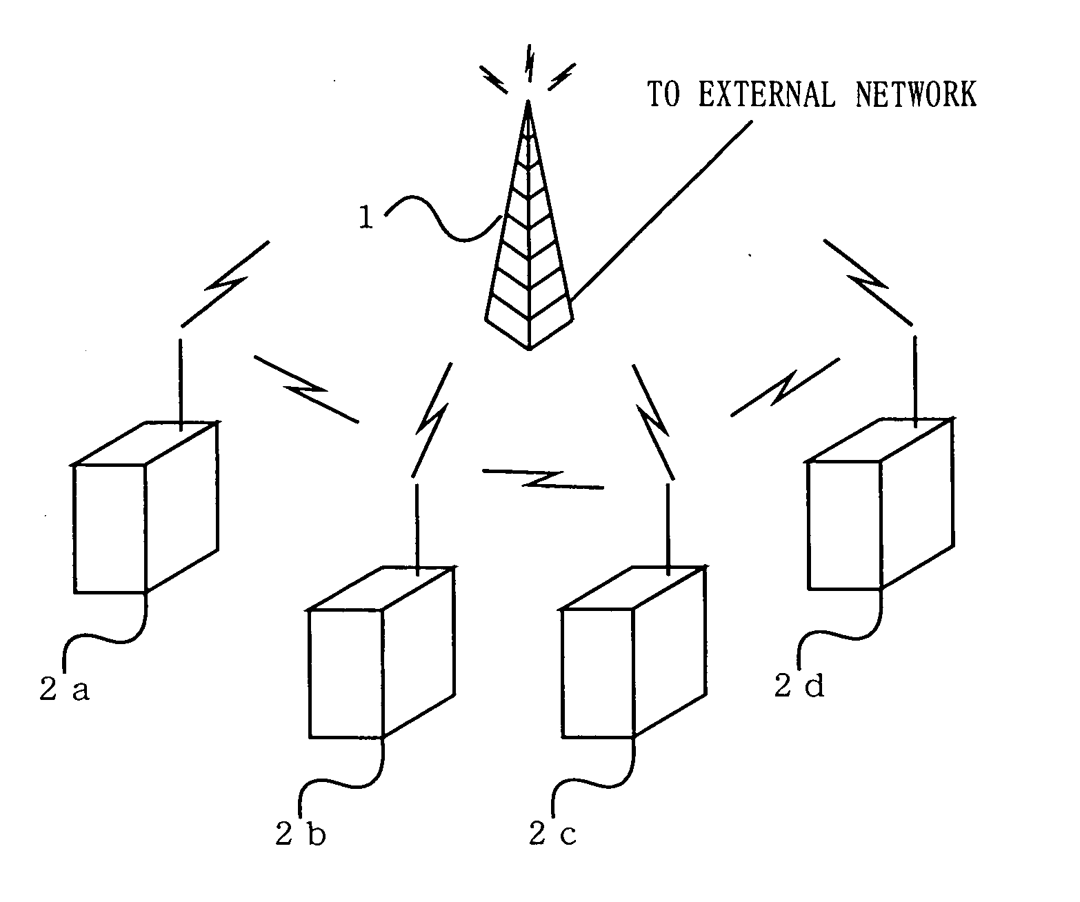
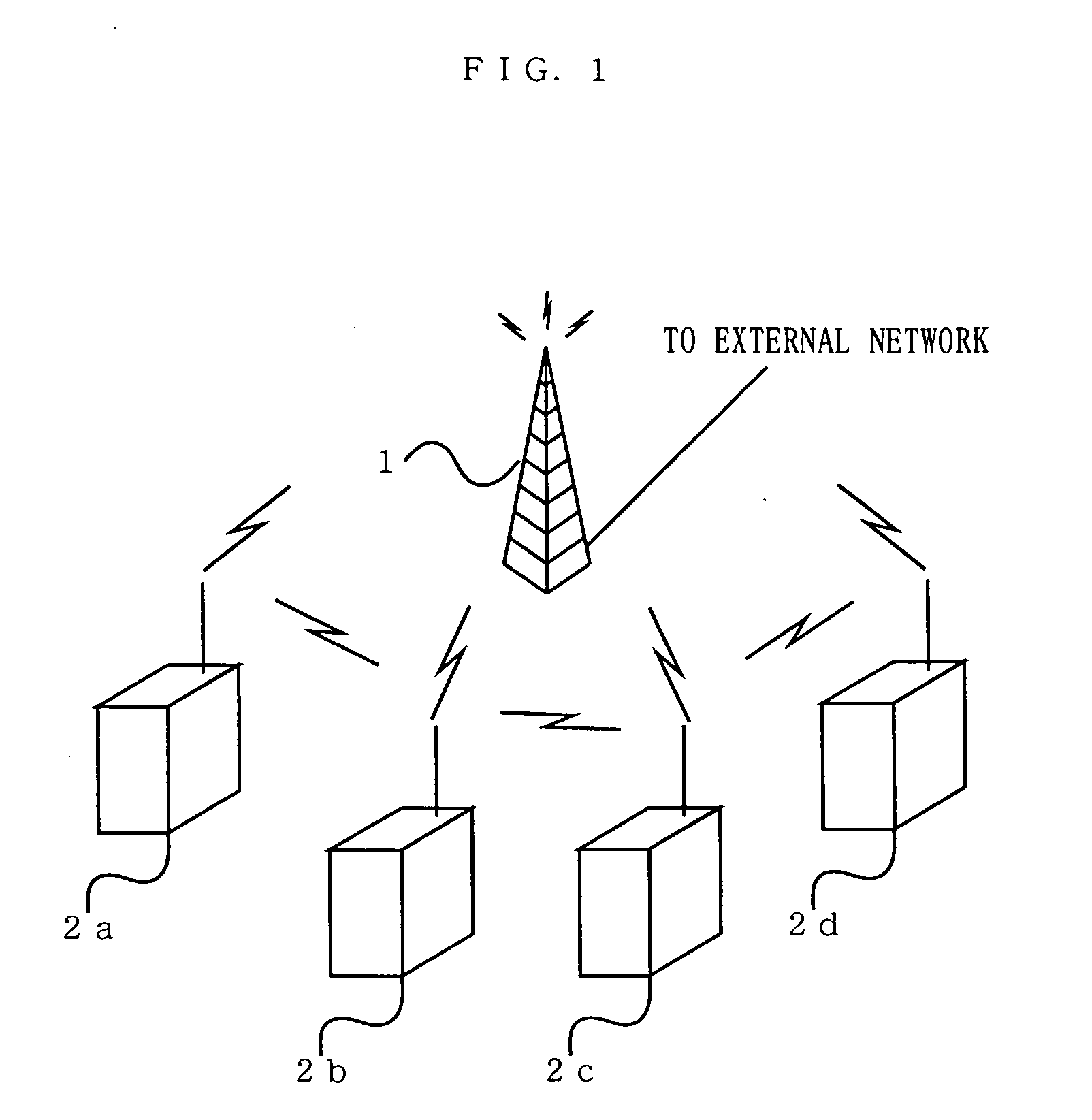
[0021] Hereinafter, a radio information communicating system according to an embodiment of the present invention will be described with reference to figures. FIG. 1 is a block diagram illustrating the entire constitution of the radio information communicating system according to an embodiment of the present invention.

[0022] The radio information communicating system shown in FIG. 1 comprises an access point (hereafter, referred to as AP) 1 and radio terminals 2a to d. This radio information communicating system is a wireless LAN system, in which radio information communications are conducted between each of the radio terminals 2a to d or the AP1. Now, the entire overview of the radio information communicating system shown in FIG. 1 will be briefly described.

[0023] In this radio information communicating system, the AP 1 and each of the radio terminals 2a to d normally perform data communication through CSMA / CA technique. Specifically, the AP 1 and the radio terminals 2a to d perfo...


PUM


Abstract

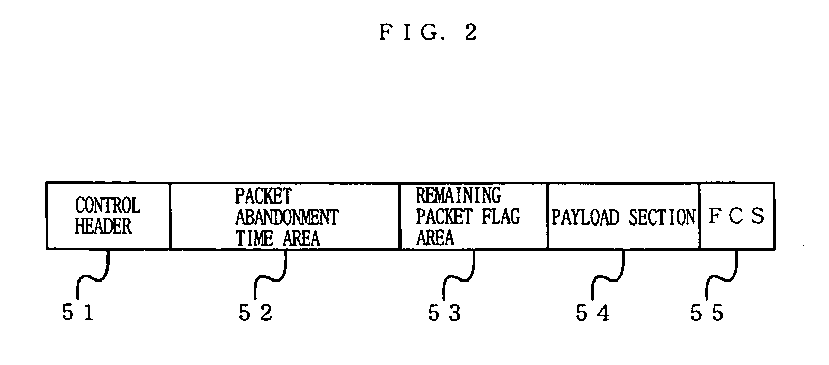
In a radio information communicating system of the present invention, a radio terminal (2a) normally transmits a packet by CSMA / CA technique. In the packet is embedded a time in which a packet to be next transmitted will be abandoned in the radio terminal (2a) due to time-out. Here, an AP 1 monitors such information and when a packet which the radio terminal (2a) is trying to transmit is about to be abandoned in the radio terminal (2a) due to time-out, grants to the radio terminal (2a) a transmission right based on polling technique. Thus, there is provided a wireless LAN system which is controllable in such a manner that specific data such as audio data will not be abandoned within a radio terminal at the transmitting end due to time-out, without imposing a heavy control load on the whole system.

Description

TECHNICAL FIELD [0001] The present invention is an invention relating to a radio information communicating system. More particularly, the present invention is an invention relating to a radio information communicating system in which one access relaying apparatus and one or more radio communication terminals constitute a local network to mutually perform radio data communication. BACKGROUND ART [0002] One information communication standard for wireless LANs is IEEE 802.11. For IEEE 802.11, DCF (Distributed Coordination Function) using CSMA / CA is proposed as a standard function. [0003] Here, under the above-mentioned DCF, a radio terminal holding a packet monitors a radio transmission line by carrier sensing and if the radio transmission line is open, performs a transmission of the packet. Conversely, if the radio transmission line is not open, the radio terminal retransmits the held packet after an interval determined by a random number based on a back-off process. Similarly, if a c...

Claims


Application Information

Patent Timeline
IPC IPC(8): H04Q7/20H04L12/28H04W72/12H04W74/02H04W74/04H04W74/06H04W74/08H04W84/12
CPCH04W74/02H04W74/0808H04W74/06
Inventor MATSUMOTO, TAKASHI
Owner PANASONIC CORP
Learn More