Ultrasound imaging apparatus having a function of selecting transmit focal points and method thereof

Inactive Publication Date: 2006-02-02
MEDINCELL
View PDF9 Cites 5 Cited by
  • Summary
  • Abstract
  • Description
  • Claims
  • Application Information

AI Technical Summary

Benefits of technology

[0007] It is, therefore, an object of the present invention to provide an ultrasound imaging apparatus having a function of selecting transmit focal points and method thereof, in which an operator may select at least one transmit focal poi

Problems solved by technology

Unlike the receive-focusing, transmit-focusing, however, cannot be performed for each point on the target object corresponding to each of all the pixels on the screen where the ultrasound image is to be displayed, and is usually performed only for the transmit focal points predetermined by a manufacturer of the diagnostic ultrasound system.
Thus, in a conventional diagnostic ultra

Method used


Image

  • Ultrasound imaging apparatus having a function of selecting transmit focal points and method thereof
  • Ultrasound imaging apparatus having a function of selecting transmit focal points and method thereof
  • Ultrasound imaging apparatus having a function of selecting transmit focal points and method thereof

Examples


Example

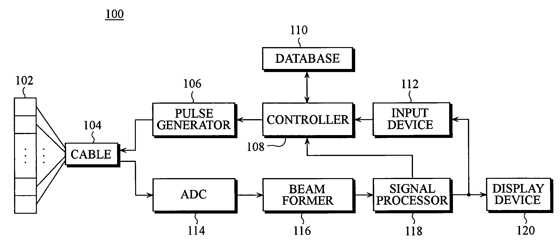
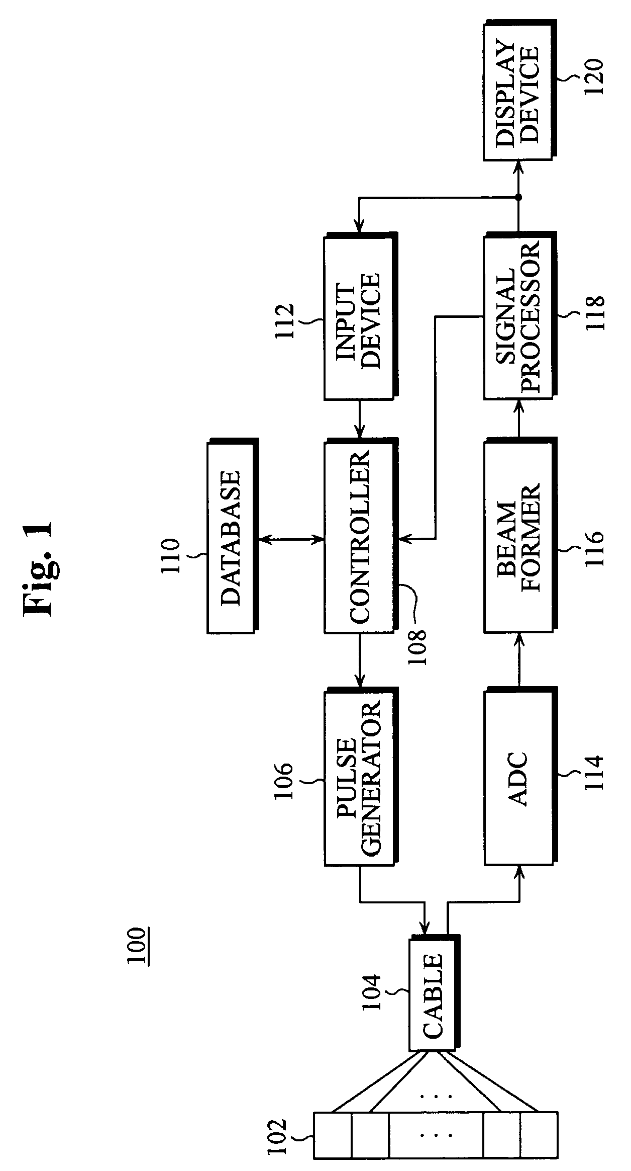
[0015] Referring to FIG. 1, a schematic block diagram of an ultrasound imaging apparatus allowing selection of transmit focal points is illustrated according to the present invention. As shown in FIG. 1, ultrasound imaging apparatus 100 includes ultrasound transducer array 102, pulse generator 106, controller 108, database 110, input device 112, analog-to-digital converter (ADC) 114, beam former 116, signal processor 118, display device 120, and further includes cables 104 that couples ultrasound transducer array 102 to pulse generator 106 and ADC 114. According to the present invention, selecting a region of interest within an ultrasound image, which is currently being observed by an operator, is essentially the same as selecting a transmit focal point where ultrasound signals are to be transmit-focused. In this context, it should be appreciated and interpreted that the terms “selection of a region of interest” and “selection of a transmit focal point” have substantially the same m...


PUM


Abstract

The present invention relates to an ultrasound imaging apparatus having a function of selecting transmit focal points and method thereof, in which an operator may select at least one transmit focal point, allowing for transmit-focusing ultrasound signals upon the selected focal point to create an ultrasound image of a target object. The ultrasound imaging apparatus includes an ultrasound transducer array, a pulse generator, a controller, a database, an input device, an analog-to-digital converter (ADC), a beam former, a signal processor, and a display device. The method for ultrasound imaging comprises the steps of: a) transmitting to a target object ultrasound signals in accordance with a predetermined initial time-delay profile; b) receiving and processing the reflected ultrasound signals from the target object to create an ultrasound image of the target object; c) displaying the created ultrasound image to allow an operator to select at least one region of interest within the displayed ultrasound image; d) in response to the operator's selection, detecting coordinates of the selected region of interest; e) determining at least one transmit focal point corresponding to the detected coordinates of the selected region of interest; f) determining at least one new time-delay profile based on each of the transmit focal points; and g) transmitting the ultrasound signals in accordance with the new time-delay profile to the target object; h) receiving and processing the reflected ultrasound signals off the target object to create an updated ultrasound image of the target object.

Description

FIELD OF THE INVENTION [0001] The present invention relates to the field of ultrasound imaging, and more particularly, to an ultrasound imaging apparatus having a function of selecting transmit focal points and method thereof, in which an operator may select at least one transmit focal point. BACKGROUND OF THE INVENTION [0002] In a diagnostic ultrasound system, “ultrasound-focusing” has to be performed for detailed observation of a desired part of an ultrasound image. This ultrasound-focusing involves “transmit-focusing,” which is to be performed while the ultrasound signals are transmitted to a target object, and “receive-focusing,” which is to be performed while the reflected ultrasound signals from the target object are received. The receive-focusing, which is to focus the ultrasound signals for all the pixels on a screen where the ultrasound image is to be displayed, has been widely used in the art of the present invention. [0003] Unlike the receive-focusing, transmit-focusing, ...

Claims


Application Information

Patent Timeline
IPC IPC(8): A61B8/06
CPCA61B8/14A61B8/463A61B8/465A61B8/467G01S7/5202G01S7/5206G01S7/52071G10K11/346G01S7/52046A61B8/461A61B8/469
Inventor KIM, CHEOL ANGYE, SANG BUMKIM, GI DUCK
Owner MEDINCELL
Why Eureka
Try Eureka