Batting glove

a glove and glove technology, applied in the field of gloves, to achieve the effect of facilitating the relationship between glove and glov

Inactive Publication Date: 2006-02-09
HILLERICH & BRADSBY COMPANY KENTUCKY
View PDF99 Cites 45 Cited by
  • Summary
  • Abstract
  • Description
  • Claims
  • Application Information

AI Technical Summary

Benefits of technology

[0007] In the development of gloves, several key elements are utilized in the design. First, on the dorsal side of the glove, the motion zones are determined by the center axis of rotation of the individual thumb, finger, hand, and wrist joints. These motion zones have been applied

Problems solved by technology

Secondly, on the palm side of the glo

Method used


Image

  • Batting glove
  • Batting glove
  • Batting glove

Examples


Embodiment Construction

A. Batting Glove

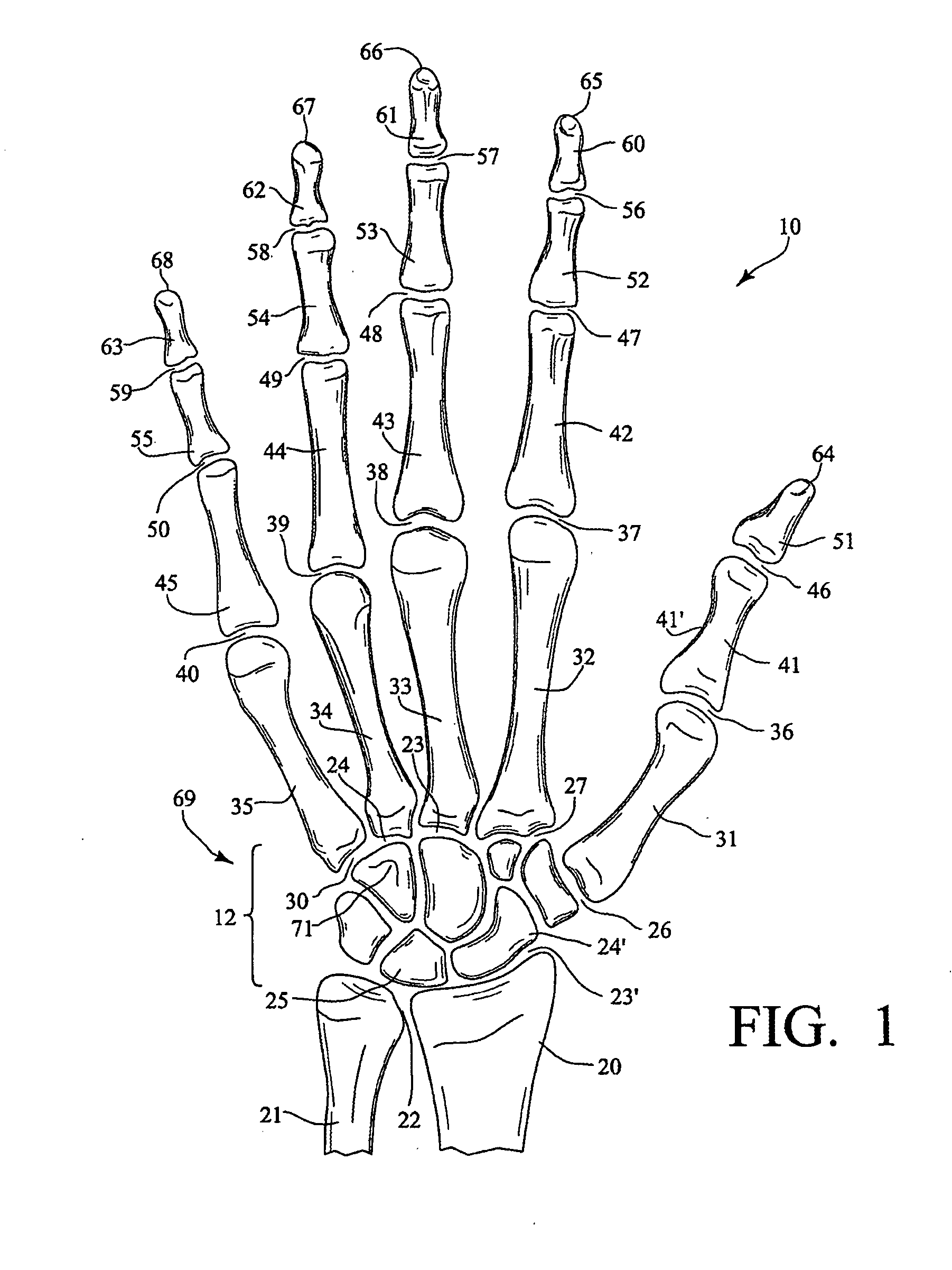
[0046]FIG. 1 is a schematic anatomical view of the bones of a right human hand 10 looking at a palm 18 side. Shown are the radius 20, ulna 21, radiocarpal joint (RC) 23′, distal radio ulnar joint (DRUJ) 22, wrist 12, thumb 64, index finger 65, long finger 66, ring finger 67, and small finger 68. The carpus 69 comprises eight carpal bones, seven of which are shown in FIG. 1 and includes the hamate bone 71 with its hook-like protrusion, the scaphoid 24′ and the lunate 25.

[0047] The thumb 64 is comprised of the distal phalanx 51, the interphalangeal joint (IP) 46, proximal phalanx 41, diaphysis of proximal phalanx 41′, metacarpalphalangeal joint (MCP) 36, metacarpal 31, and carpometacarpal joint (CMC) 26.

[0048] The index finger 65 is comprised of the distal phalanx 60, distal interphalangeal joint (DIP) 56, middle phalanx 52, proximal interphalangeal joint (PIP) 47, proximal phalanx 42, metacarpalphalangeal joint (MCP) 37, metacarpal 32, and carpometacarpal joint (CMC...


PUM


Abstract

A batting glove particularly for baseball and softball includes padding along the palmar side of at least the proximal ends of the metacarpals of the ring finger and the small finger. Padding is absent over the hook of the hamate and preferably the carpometacarpal joints of the ring finger and the small finger.

Description

CROSS REFERENCE TO RELATED APPLICATIONS [0001] This application is a continuation-in-part of and claims priority to and benefit from, currently pending U.S. patent application Ser. No. 10 / 670,859 filed Sep. 25, 2003 which is a continuation-in-part of patent application Ser. No. 10 / 001,325 filed Oct. 25, 2001, now U.S. Pat. No. 6,701,530 issued Mar. 9, 2004, which is a continuation-in-part of and claims priority to and benefit from U.S. patent application Ser. No. 09 / 867,084 filed May 29, 2001, now U.S. Pat. No. 6,389,601 issued on May 21, 2002, which is a continuation of and claims priority to and benefit from U.S. patent application Ser. No. 09 / 491,742 filed Jan. 27, 2000 now U.S. Pat. No. 6,253,382 issued on Jul. 3, 2001.BACKGROUND OF THE INVENTION [0002] 1. Field of the Invention [0003] This invention relates to gloves for the human hand which are worn when playing sports such as baseball, softball, or working and the like. In one aspect, this invention relates to a batting glove...

Claims


Application Information

Patent Timeline
IPC IPC(8): A41D19/00
CPCA41D19/015A41D19/01517A41D19/01523A63B71/143A63B2243/0045A63B2209/10A63B2243/0004A63B2243/0008A63B2243/0029A63B71/146A63B2102/24A63B2102/32A63B2102/18A63B2102/182A41D2300/32
Inventor KLEINERT, JAMES M.
Owner HILLERICH & BRADSBY COMPANY KENTUCKY
Why Eureka
Try Eureka