
Refrigerating device comprising waste heat utilization equipment

Inactive Publication Date: 2006-02-09
DENSO CORP +1
View PDF6 Cites 39 Cited by
  • Summary
  • Abstract
  • Description
  • Claims
  • Application Information

AI Technical Summary

Benefits of technology

[0010] Due to this, it is possible to operate the refrigerating cycle (200) using the compressor (210) even when the expansion device (320) cannot be operated because a sufficient amount of waste heat cannot be obtained from the heat generating device (10) and, therefore, air-conditioning is possible.
[0012] In a third aspect of the present invention according to the first or second aspect, it is preferable to use the output of an expansion device (320) for generating electricity and, due to this, it is possible to reduce the load of generating electricity imposed on an internal combustion engine (10).
[0013] In a fourth aspect of the present invention, it may be possible to use the output of an expansion device (320) for driving a pump (330) and, due to this, it is possible to reduce the energy for driving the pump (330).
[0014] A fifth aspect of the present invention is characterized in that a compressor (210) is driven by an internal combustion engine (10) and, due to this, regardless of the presence or absence of the output of an expansion device (320), it is possible not only to operate the compressor (210) but also to effectively utilize the waste heat of the internal combustion engine (10) in accordance with the output of the expansion device (320).
[0017] According to this aspect, it is also possible to reduce the load of generating electricity imposed on an internal combustion engine (10) and, as a result, it is possible to improve the fuel consumption efficiency of a vehicle as a whole.

Problems solved by technology

However, in the above-mentioned refrigerating device, air-conditioning is not possible when waste heat cannot be recovered such as when an internal combustion engine is in a warm-up state.
For example, in the case where the refrigerating device is applied to a vehicle, even if the cooling of the vehicle is required after it has been exposed to the heat of the sun in summer, and despite a strong demand for air-conditioning, it is not possible to perform air-conditioning until warm-up of the engine is completed because the compressor cannot be driven by an expansion device.

Method used


Image

  • Refrigerating device comprising waste heat utilization equipment
  • Refrigerating device comprising waste heat utilization equipment
  • Refrigerating device comprising waste heat utilization equipment

Examples


first embodiment

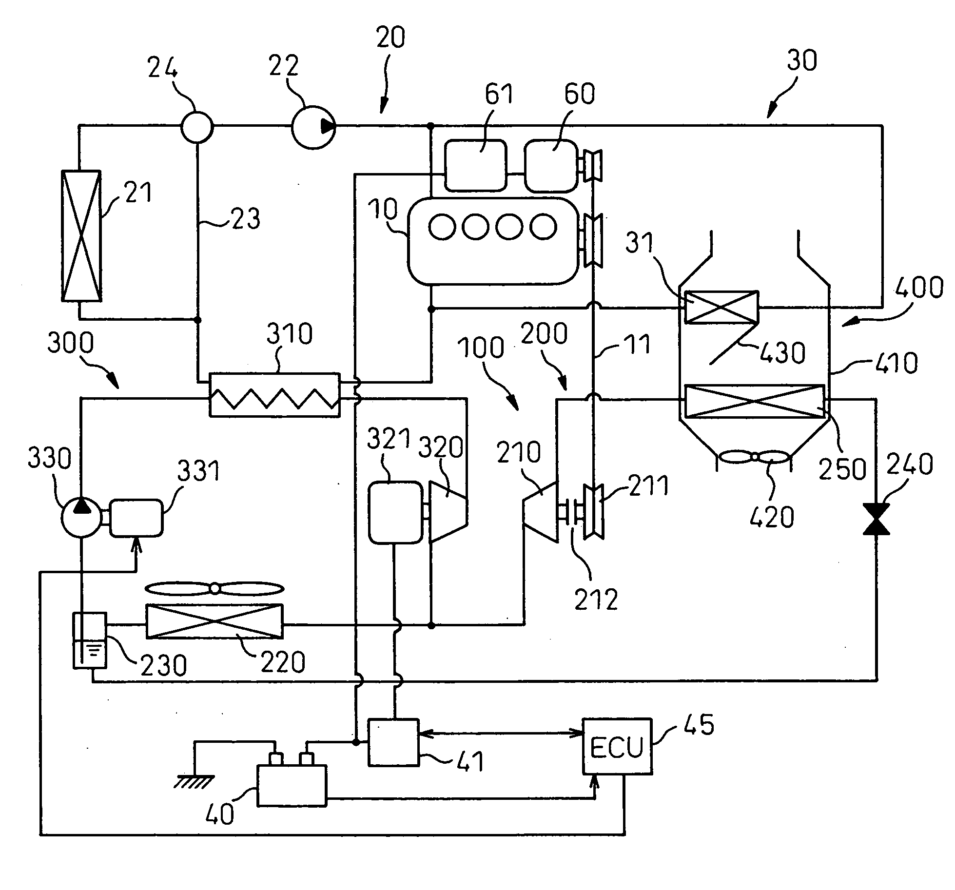
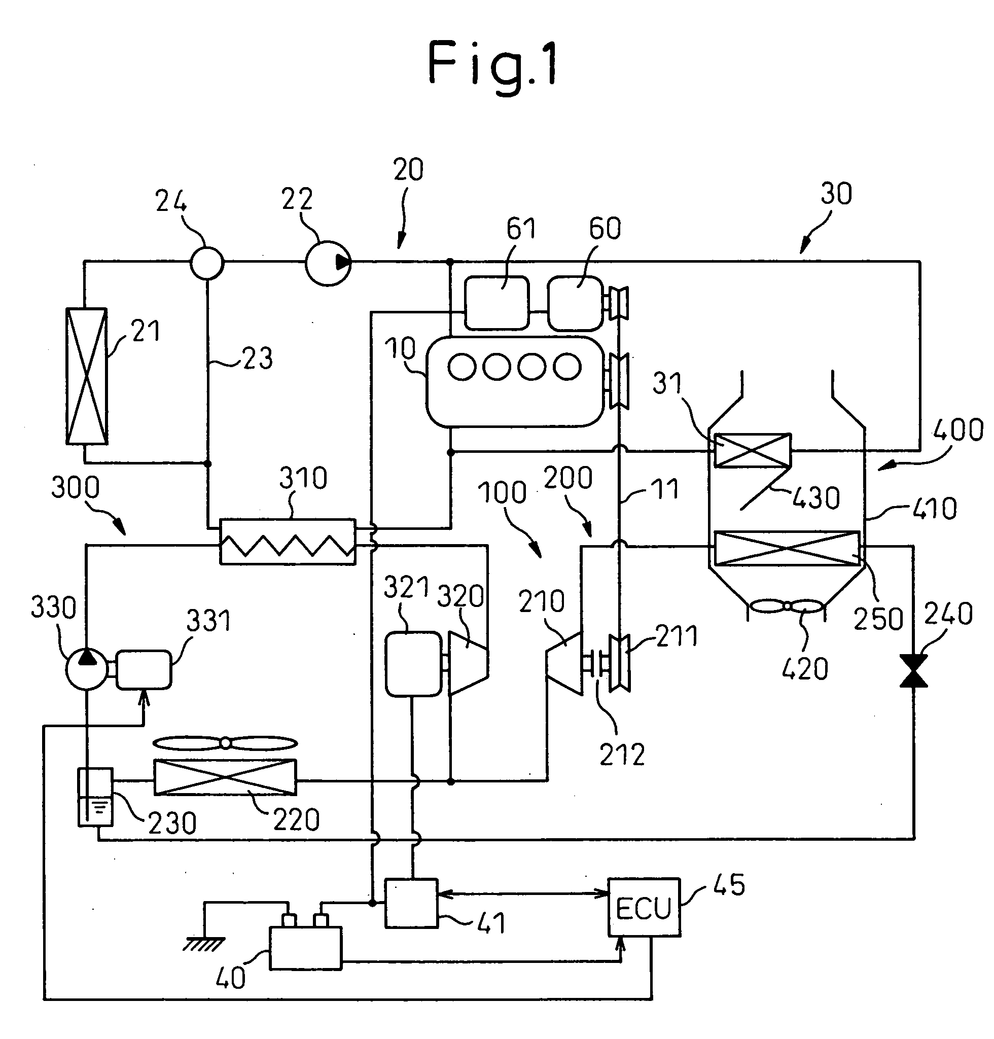
[0026] A first embodiment of the present invention is shown in FIG. 1 and a concrete configuration thereof is explained first. In this embodiment, a refrigerating device comprising waste heat utilization equipment (hereinafter, referred to as a refrigerating device) 100 of the present invention is applied to a vehicle using an engine 10 as a drive source. The refrigerating device 100 is provided with a refrigerating cycle 200 and a Rankine cycle 300 and the respective operations of the respective cycles 200 and 300 are controlled by a control unit, not shown.

[0027] The engine 10 is a water-cooling internal combustion engine (corresponding to a heat generating device in the present invention) and a radiator circuit 20 for cooling the engine 10 by means of circulation of engine cooling water and a heater circuit 30 for heating conditioned air using the cooling water (hot water) as a heat source, are provided.

[0028] The radiator circuit 20 is provided with a radiator 21 and the radia...

second embodiment

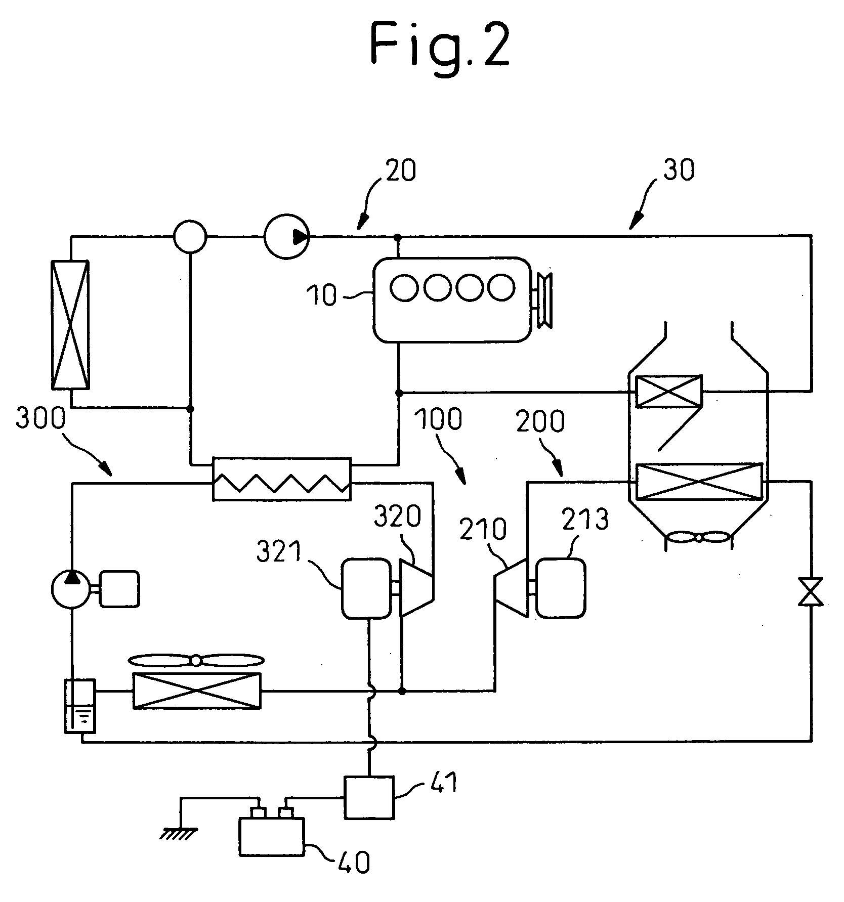
[0050] A second embodiment of the present invention is shown in FIG. 2. In the second embodiment, the drive means of the compressor 210 in the first embodiment is modified. In other words, here, the compressor 210 is connected to an electric motor 213 (that is, the compressor is an electric compressor) and is driven by the drive force of the electric motor 213. Due to this, the same effect as that in the first embodiment can be obtained.

[0051] The compressor 210 may be a hybrid compressor capable of selecting at least one of the engine 10 and the electric motor 213 as a drive means.

third embodiment

[0052] A third embodiment of the present invention is shown in FIG. 3. In the third embodiment, the drive source of the pump 330 in the first embodiment is modified. Here, instead of the electric motors 321 in the first and second embodiments, an electric generator 322 having both functions of an electric motor and an electric generator is connected to the expansion device 320, and further, the pump 330 and the electric generator 322 are connected to each other.

[0053] In the third embodiment, when the Rankine cycle is operated, first the electric generator 322 is operated as an electric motor to drive the pump 330. Then, when a sufficient amount of waste heat can be obtained from the engine 10 and the drive force of the expansion device 320 exceeds the power of the pump 330, the electric-motor driven electric generator 322 is operated as an electric generator to generate electricity.

[0054] Due to this, the dedicated drive source (the electric motors 331 in the above-mentioned firs...


PUM


Abstract

In a refrigerating device comprising waste heat utilization equipment having: a refrigerating cycle 200 formed by sequentially connecting a compressor 210, a condenser 210, an expansion valve 240, and an evaporator 250; and a Rankine cycle 300 formed by sequentially connecting a heater 310 using the waste heat of a heat generating device (for example, an internal combustion engine) 10 as a heating source, an expansion device 320, the above-mentioned condenser 220, and a pump 330, in which the drive shafts of the compressor 210 and the expansion device 320 are separated from each other. Then, the output of the expansion device 320 is used mainly for generating electricity.

Description

BACKGROUND OF THE INVENTION [0001] 1. Field of the Invention [0002] The present invention relates to a refrigerating device comprising waste heat utilization equipment, for recovering power by utilizing waste heat of a heat generating device, and is preferably applied to a vehicle having an internal combustion engine. [0003] 2. Description of the Related Art [0004] As a conventional refrigerating device, for example, one disclosed in Patent document 1 is known. The refrigerating device has a Rankine cycle, utilizing cooling waste heat included in a cooling medium, such as a cooling water, for cooling an internal combustion engine as a heat generating device, and a refrigerating cycle, and the output shaft of an expansion device in the Rankine cycle is connected to the shaft of a compressor in the refrigerating cycle. Due to this, it is possible to drive the compressor by using power (output of the expansion device) recovered in the Rankine cycle and air-conditioning is enabled while...

Claims


Application Information

Patent Timeline
IPC IPC(8): F25B27/00
CPCB60H1/3222F25B27/02B60H2001/3297Y02A30/274
Inventor INABA, ATSUSHIYAMANAKA, YASUSHIHISANAGA, SHIGERUYAMANAKA, TAKASHIASA, HIRONORIKISITA, HIROSHI
Owner DENSO CORP
Learn More