Motor cooling structure for electric vehicle

Inactive Publication Date: 2006-02-09
HONDA MOTOR CO LTD
View PDF9 Cites 26 Cited by
  • Summary
  • Abstract
  • Description
  • Claims
  • Application Information

AI Technical Summary

Benefits of technology

[0008] It is accordingly an object of the present invention to provide a motor cooling structure for an

Problems solved by technology

However, at present, the electric vehicle also has various disadvantages, including a cruising distance that is short because of the limit of a battery capacity, and the cost per mileage of the unit energy is high causing low economy.
However, the above-mentioned conventional cooling structure is adapted to a power unit for a vehicle ha

Method used


Image

  • Motor cooling structure for electric vehicle
  • Motor cooling structure for electric vehicle
  • Motor cooling structure for electric vehicle

Examples


Example

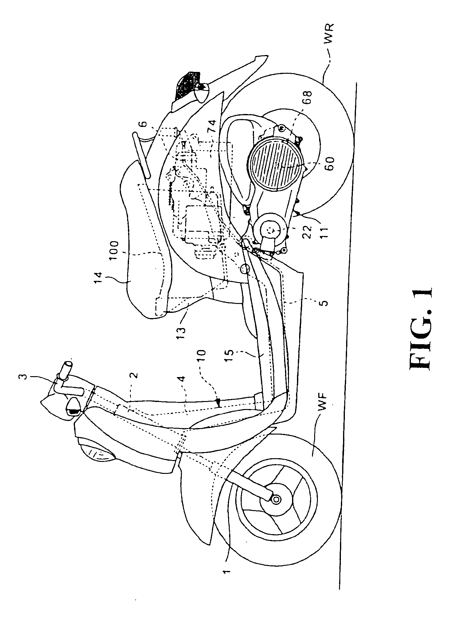
[0031]FIG. 1 is a side view of a preferred embodiment of a scooter type hybrid vehicle to which the motor cooling structure of the present invention is applied.

[0032] The hybrid vehicle has a front fork 1 for rotatably supporting a front wheel WF at a front portion of a vehicle body. The front fork 1 is pivotably supported to a head pipe 2 so as to be steerable by the operation of a steering handle 3. A down pipe 4 is mounted on the head pipe 2 so as to extend rearward and downward therefrom. An intermediate frame 5 extends substantially horizontally from the lower end of the down pipe 4. A rear frame 6 extends rearward and upward from the rear end of the intermediate frame 5.

[0033] Thus, the head pipe 2, the down pipe 4, the intermediate frame 5, and the rear frame 6 constitute a body frame 10. A power unit 11 including an engine and a motor as power sources and a power transmitting mechanism is pivotably mounted at one end thereof to the body frame 10. A rear wheel WR as a drive...


PUM


Abstract

A motor cooling structure for efficiently cooling a driving motor in a power unit case of the electric vehicle includes a transmission case cover having an air filter mounted on a side surface of a transmission case adjacent to a fan, and a ventilation gap defined between a rear portion of the transmission case cover and the transmission case. The transmission case cover includes a cooling air inlet facing the ventilation gap. When the fan is rotated in synchronism with a crankshaft, an outside cooling air is introduced from the cooling air inlet into the transmission case cover and then passes through the air filter to enter the transmission case, thereby forcibly cooling a transmission. Thereafter, a part of the cooling air is discharged from a central air outlet to the outside of the transmission case, and the remaining cooling air is drawn to the driven portion of the transmission.

Description

CROSS-REFERENCE TO RELATED APPLICATION [0001] The present application claims priority under 35 U.S.C. §119 to Japanese Patent Application No. 2004-229416, filed Aug. 5, 2004, the entire contents of which are hereby incorporated by reference. BACKGROUND OF THE INVENTION [0002] 1. Field of the Invention [0003] The present invention relates to a motor cooling structure for an electric vehicle using a driving motor as a power source or an auxiliary power source for running. [0004] 2. Description of Background Art [0005] An electric vehicle using an electric motor as a power source has various advantages such that no air pollution occurs, noise pollution is suppressed, and acceleration / deceleration response is better as compared with a conventional automobile using an engine as a power source. However, at present, the electric vehicle also has various disadvantages, including a cruising distance that is short because of the limit of a battery capacity, and the cost per mileage of the uni...

Claims


Application Information

Patent Timeline
IPC IPC(8): F01P1/02B60K6/485B60K11/06B60L3/00B62M7/12B62M23/02H02K9/06
CPCB60K1/00B60K2001/003F01P1/06F01P5/06Y02T10/641F16H57/0415F16H57/0489H02K7/14H02K9/06F01P2050/16B60L15/2054H02K7/006B60L2200/12B60L2210/10B60L2210/40B60L2240/421B60L2240/441B60L2240/486B60L2240/507B60L2260/26Y02T10/70B60L50/16B60L50/66Y02T10/64Y02T10/72Y02T10/7072
Inventor TSUKADA, YOSHIAKIOZEKI, TAKASHIIIMURO, AKIHIROISHIKAWA, TOMOMI
Owner HONDA MOTOR CO LTD
Why Eureka
Try Eureka