Fuel delivery pipe

a technology of fuel delivery pipe and which is applied in the direction of liquid fuel feeders, machines/engines, mechanical equipment, etc., can solve the problems of absorbing vibrations generated in the fuel delivery pipe or the underfloor piping up to the tank, pressure pulsation in the interior and noise imparting an unpleasant feeling to the driver and passengers, etc., to suppress the resonance of the fuel delivery pipe body, suppress the propagation of mechanical vibrations, and suppress radiation nois

Active Publication Date: 2006-02-09
USUI KOKUSAI SANGYO KAISHA LTD
View PDF9 Cites 12 Cited by
  • Summary
  • Abstract
  • Description
  • Claims
  • Application Information

AI Technical Summary

Benefits of technology

[0018] Accordingly, an object of the invention is to provide a fuel delivery pipe which makes it possible to control the frequency of the pressure fluctuation in the flow route of fuel in conjunction with fuel injection from the injector, and which is capable of suppressing the direct transmission to the fuel delivery pipe body of high-frequency noise such as clattering noise generated when an injector spool is seated onto a valve seat or the like, thereby making it possible to suppress to a small level the radiation of the high-frequency noise to the fuel delivery pipe body and to the outside.
[0024] In addition, the fuel delivery pipe body may include a fixing member which is capable of suppressing the deformation of the fuel delivery pipe body and which is connected and fixed to the fuel delivery pipe body to straddle an outer surface of the tubular joint.
[0025] In addition, the fuel delivery pipe body and the tubular joint may be fixed by welding or brazing with the interposition of an interposed member capable of suppressing the deformation of the fuel delivery pipe body, and the outlet port of the fuel delivery pipe body and the inlet port of the tubular joint may be communicated through a through hole provided in the interposed member.
[0030] The fuel delivery pipe in accordance with the invention is constructed as described above, in the pressure pulsation caused by the fuel injection by the injector, which constitutes the problem of the radiation noise, since the length of a fuel flow member from the tip of the injector to the fuel delivery pipe body is elongated by the interposition of the tubular joint between the holder portion of the injector and the fuel delivery pipe body, the natural pulsation frequency of this flow member and the natural resonance frequency of the fuel delivery pipe body can be made different. Accordingly, it becomes possible to suppress the resonance of the fuel delivery pipe body due to the pressure pulsation from the injector side. Further, the mechanical vibrations due to the operation of the injector, which constitutes a problem in the radiation noise separately from the pressure pulsation, can be absorbed as the tubular joint which is formed to be elongated undergoes flexural deformation, making it possible to suppress the propagation of the mechanical vibrations to the fuel delivery pipe body. Accordingly, the high-frequency noise of not less than several kilohertz such as clattering noise, which is generated when the injector spool is seated onto the valve seat or the like after fuel injection, is prevented from being amplified by the fuel delivery pipe body, thereby making it possible to suppress the occurrence of the radiation noise to the outside to a small level.

Problems solved by technology

Since this returnless type fuel delivery pipe does not have the piping for returning the excess fuel to the fuel tank, if the interior of the fuel delivery pipe is decompressed by the fuel injection from the injectors into the intake pipes or cylinders of the engine, pressure waves which occur due to this sharp decompression and the stopping of the fuel injection causes pressure pulsation in the interior of the fuel delivery pipe.
As a result, this pressure pulsation is propagated to the vehicle compartment as noise through clips retaining the underfloor piping to underneath the floor, and this noise imparts an unpleasant feeling to the driver and passengers.
Thus, vibrations generated in the fuel delivery pipe or the underfloor piping up to the tank are absorbed.
However, the pulsation damper and the vibration absorbing clips are expensive, and the number of parts increases, entailing a higher cost.
Further, a new problem has occurred in the securing of the installation space.
On the other hand, in the conventional techniques shown in patent documents 1 to 6, although there is an effect in absorbing the pressure pulsation, there has been a problem in that there can occur the trouble that noise on the high-frequency side of not less than several kilohertz such as clattering noise is generated when an injector spool is seated onto a valve seat or the like as the injector is opened and closed during the fuel injection, and this noise is amplified by the absorbing surface and is radiated to the outside.
However, according to the method in which a bead is provided on the wall surface, it is technically difficult to make adjustment such that the high-frequency side noise will not be radiated while being provided with the flexibility capable of suppressing the pressure pulsation of a fluid.
In addition, if a circular pipe is joined to the flat wall surface, the mutual contact becomes linear contact, and joining stability is insufficient, so that there has been a possibility that the high-frequency noise reverberates inside the circular pipe.

Method used


Image

  • Fuel delivery pipe
  • Fuel delivery pipe
  • Fuel delivery pipe

Examples


1st embodiment

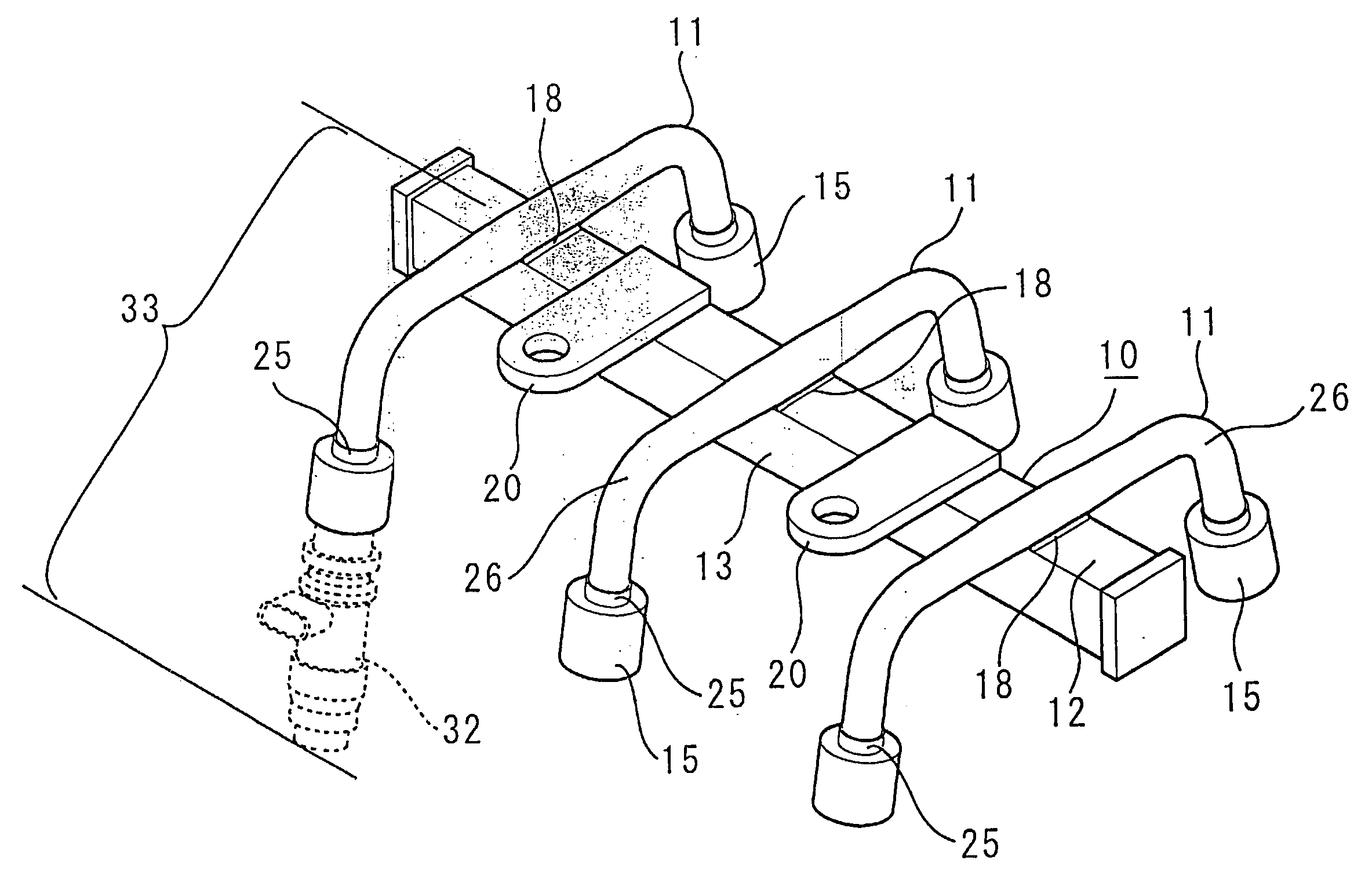
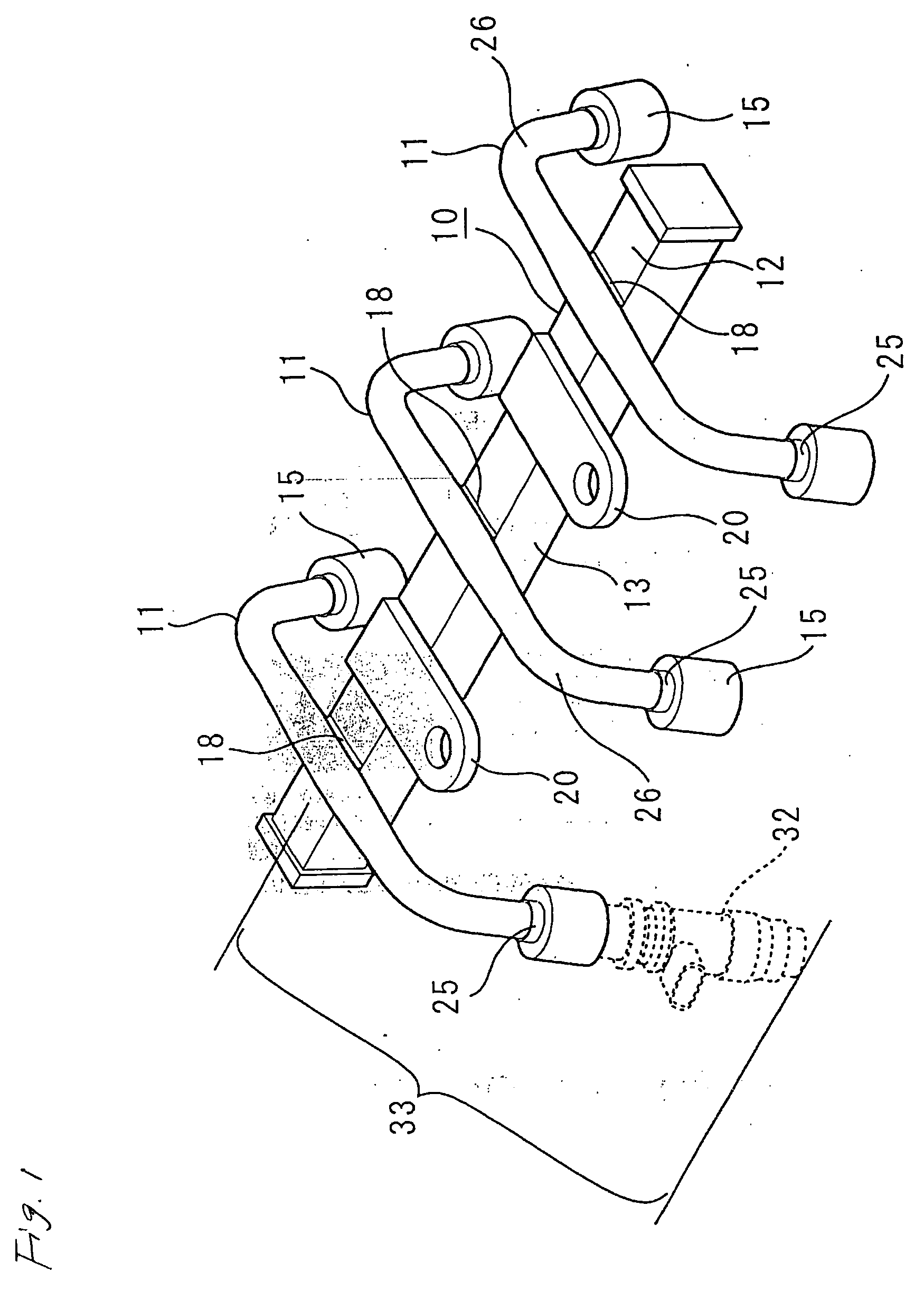
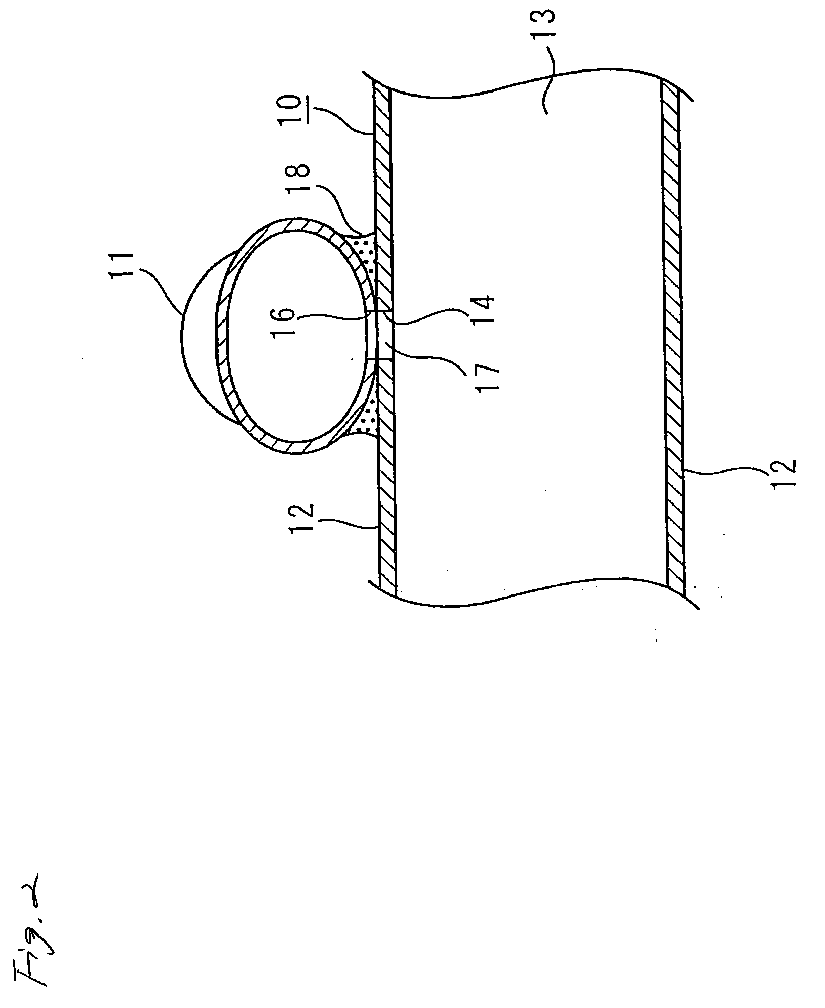
[0065] Hereafter, referring to FIGS. 1 and 2, a detailed description will be given of a first embodiment of the fuel delivery pipe in accordance with the invention. Reference numeral 10 denotes a fuel delivery pipe body whose cross-sectional shape perpendicular to the pipe axis is square. A fuel inlet pipe (not shown) is connected to one end of this fuel delivery pipe body 10, and this fuel inlet pipe is joined to a fuel tank (not shown) through underfloor piping (not shown). Fuel in this fuel tank is transferred to the fuel inlet pipe through the underfloor piping, and flows into the fuel delivery pipe body 10 from the fuel inlet pipe. The fuel in the fuel delivery pipe body 10 is injected into intake pipes and cylinders from injectors 32 respectively connected to tubular joints 11 which will be described later.

[0066] The above-described fuel delivery pipe body 10 has four walls including upper and lower walls 12 and both side walls 13, which are elongated in the direction of the ...

2nd embodiment

[0077] In a second embodiment shown in FIGS. 4 and 5, in the same way as in the first embodiment, the tubular joint 11 having the holder portions 15 respectively provided at both pipe end portions 25 is disposed in contact with the upper or lower wall 12 of the fuel delivery pipe body 10, and the outlet port 14 which is open in this upper or lower wall 12 and the inlet port 16 which is open in the tubular joint 11 are communicated with each other to form the flow path 17. The fuel delivery pipe body 10 and the tubular joint 11 are fixed by welding or brazing at the peripheries of this flow path 17, thereby connecting the fuel delivery pipe body 10 and the tubular joint 11. By adopting such a structure, in the second embodiment as well, it is possible to suppress the amplification of the high-frequency noise in the fuel delivery pipe body 10, and suppress the radiation of the ration noise to the outside to a low level.

[0078] Further, in the second embodiment, the connecting portions...

3rd embodiment

[0080] A description will be given of a third embodiment of the invention with reference to FIGS. 6 and 7. Although in the above-described first and second embodiments the fuel delivery pipe body 10 and the tubular joint 11 are directly fixed by welding or brazing, in this third embodiment a solid interposed member 22 made of a metal plate and capable of suppressing the deformation of the contacting upper or lower wall 12 of the fuel delivery pipe body 10 is interposed between the fuel delivery pipe body 10 and the tubular joint 11. This interposed member 22 is connected and fixed to an outer surface of the fuel delivery pipe body 10 by welding or brazing, and the tubular joint 11 is connected and fixed to an upper surface of this interposed member 22 by welding or brazing. By virtue of such an arrangement, the respective surfaces of the upper or lower wall 12 of the fuel delivery pipe body 10, the interposed member 22, and the tubular joint 11 are disposed in parallel and are conne...


PUM


Abstract

An inlet port 16 communicating with the interior of a fuel delivery pipe body 10 to introduce fuel is made open in a center of a tubular joint 11 having a smaller diameter than an inside diameter of a holder portion 15 of an injector 32 connected to a respective pipe end portion 25, and a length from a center of this inlet port 16 to the pipe end portion 25 is set to 30 to 1000 mm, to thereby form the tubular joint 11. The tubular joint 11 and the fuel delivery pipe body 10 are fixed such that the inlet port 16 of this tubular joint 11 is communicatable with the interior of the fuel delivery pipe body 10.

Description

[0001] The present application claims foreign priority based on Japanese Patent Application No. 2004-226693, filed on Aug. 03, 2004, the contents of which is incorporated herein by reference in its entirety, and concurrently with the filing of this patent application. BACKGROUND OF THE INVENTION [0002] The present invention relates to a fuel delivery pipe for supplying fuel supplied from a fuel booster pump of an electronic fuel injection type automotive engine to respective intake passages of the engine through an injector, and is aimed at reducing the radiation noise generated during fuel injection from the injector. [0003] Conventionally, fuel delivery pipes are known in which a plurality of injectors are provided to supply fuel such as gasoline to a plurality of cylinders of the engine. In this fuel delivery pipe, fuel introduced fro a fuel tank through underfloor piping is sequentially injected into a plurality of intake pipes or cylinders of the engine from the plurality of in...

Claims


Application Information

Patent Timeline
Patent Type & Authority Applications(United States)
IPC IPC(8): F02M55/02
CPCF02M55/025F02M69/465F02M69/462F02M55/04
Inventor WATANABE, EIJIHAYASHI, KOICHIUSUI, SHOICHIRO
Owner USUI KOKUSAI SANGYO KAISHA LTD
Why Eureka
Try Eureka