Whipstock assembly and method of manufacture

Inactive Publication Date: 2006-02-09
WEATHERFORD TECH HLDG LLC +1
View PDF16 Cites 37 Cited by
  • Summary
  • Abstract
  • Description
  • Claims
  • Application Information

AI Technical Summary

Benefits of technology

[0034] The raised surface feature is fabricated from a material that is capable of withstanding the stresses of a milling operation. The rails (or other raised surface) are also positioned in sufficient proximity to one another to substantially prevent the milling bits from frictionally engaging the perforating plate during the milling operation. At the same time, because the rails are not a continuous surface, they permit perforations to more uniformly penetrate the perforation plate of the whipstock. In this respect, the perforation plate surface is exposed between the rails and is fabricated from a softer material than is the raised surface. Alternatively, the rails define a thicker portion of material, meaning that the perforation plate is more readily penetrated by perforation shots between the rails.
[0035] The present inve

Problems solved by technology

However, in prior art whipstock designs, the perforation plate 110 has a limited pressure capacity, i.e., burst pressure, because the perforation plate 110 simply represents a plate welded onto a formed ramp in the whipstock body.
While such a composition aids in perforation of the whipstock 80, it also reduces the durability of the whipstock 80 during the milling operation.
Still further, the uneven face surface of the perforation plate 110 resulting from sacrifice during the milling process reduces the effectiveness of the shaped charges.
Additionally, the prior art whipstock is difficult to manufacture.
In this respect, the joining of the thin perforation plate

Method used


Image

  • Whipstock assembly and method of manufacture
  • Whipstock assembly and method of manufacture
  • Whipstock assembly and method of manufacture

Examples


Embodiment Construction

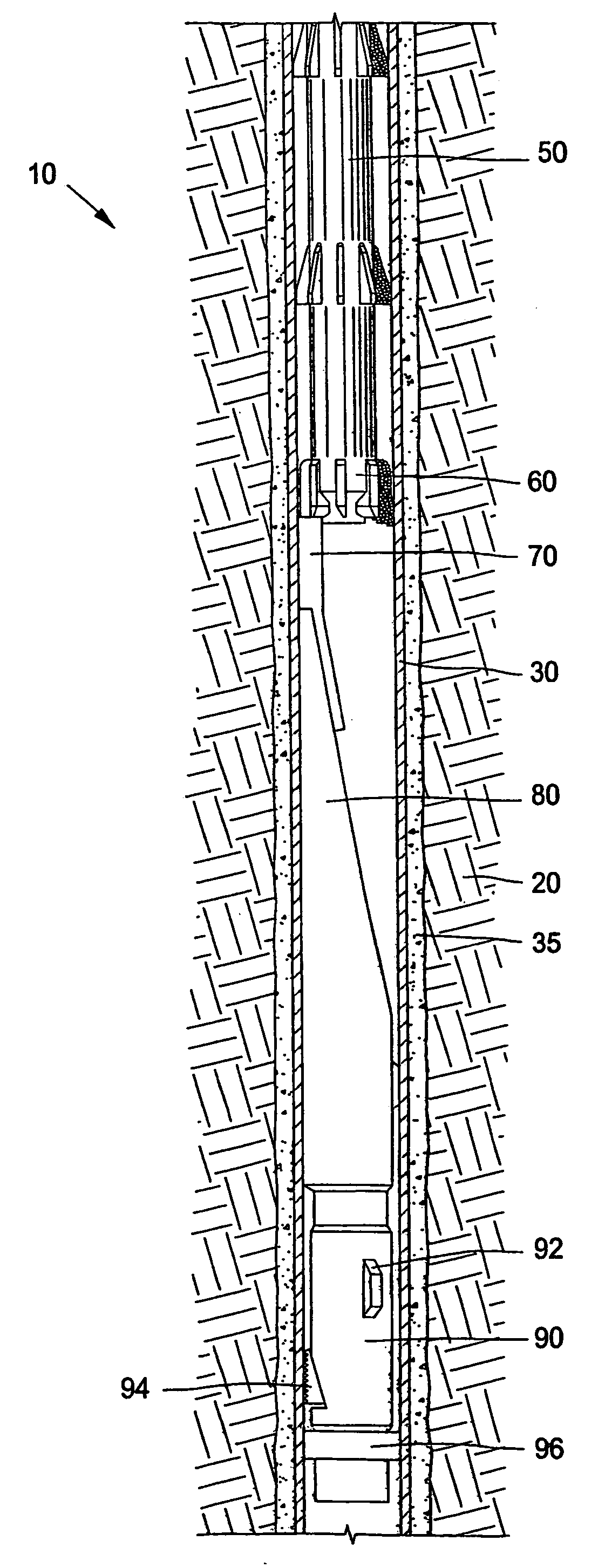
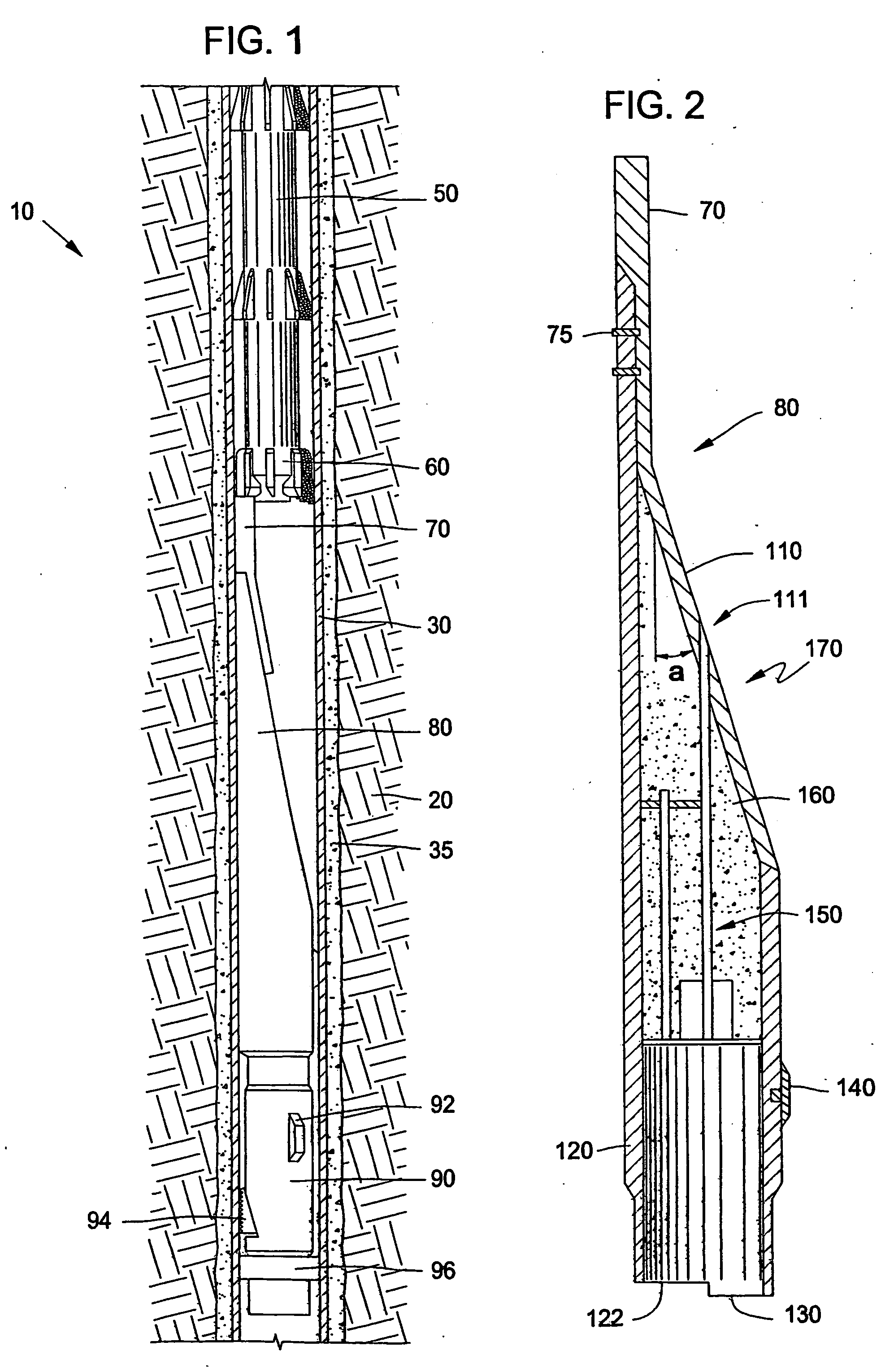
[0052]FIG. 6 illustrates one embodiment of the whipstock assembly 100 of the present invention for milling a window W in a wellbore. The whipstock 100 has a top end and a bottom end 122. The bottom end 122 defines a base for the whipstock 100. The top end defines a concave-shaped member 111 and a back cover member 120. The back cover member 120 is an arcuate body. Together, the concave-shaped member 111 and the back cover member 120 form an outer metal shell and a generally hollow inner cavity therein.

[0053] The concave-shaped member 111 receives a milling bit (not shown) as the bit is urged downwardly into the wellbore during a milling operation. At the same time, the concave-shaped member 111 urges the milling bit outwardly against a surrounding tubular, e.g. casing (not shown) in order to form the window.

[0054] The inner cavity (not seen) within the whipstock 100 is in fluid communication with formation fluids below the hollow base 122. However, the concave-shaped member 111 an...


PUM


Abstract

The present invention discloses a whipstock assembly (100) for use in forming a lateral borehole from a parent wellbore. The whipstock assembly comprises a body (122) and a deflection member 120) above the body. The deflection member includes aconcave portion (111) for deflecting a milling bit during a milling operation. Disposed on a perforation plate (110) portion of the concave portion is a raised surface feature (116). The raised surface supports a milling bit above the perforation plate portion during a milling operation. This, in turn, substantially prevents frictional contact between the milling bits and the perforation plate portion during a milling operation. The present invention also provides a novel method for manufacturing a whipstock in which a cavity portion is formed behind the perforation plate by milling out the backside of the deflection member and then joining a second back cover member to the whipstock body to complete the assembly.

Description

CROSS-REFERENCE TO RELATED APPLICATIONS [0001] This application for letters patent claims priority from an earlier-filed U.S. provisional patent application entitled “Whipstock Assembly for Forming a Window Within a Wellbore Casing.” That application was filed on Apr. 12, 2002 and was assigned Application No. 60 / 372,004. The provisional application is herein incorporated by reference.BACKGROUND OF THE INVENTION [0002] 1. Field of the Invention [0003] This invention is related to the practice of sidetrack drilling for hydrocarbons. More specifically, this invention pertains to a whipstock assembly for creating a window within a wellbore casing. More particularly still, the invention pertains to a whipstock that more easily permits penetration of perforation shots through the perforation plate. [0004] 2. Description of the Related Art [0005] In recent years, technology has been developed which allows an operator to drill a primary vertical well, and then continue drilling an angled la...

Claims


Application Information

Patent Timeline
IPC IPC(8): E21B7/06E21B7/08E21B17/10
CPCE21B17/1007E21B7/061
Inventor CARTER, THURMANBREDLINGER, THOMASMBRUNNERT, DAVIDJ
Owner WEATHERFORD TECH HLDG LLC
Why Eureka
Try Eureka