Battery device of vehicle power supply

a battery and power supply technology, applied in the direction of batteries, safety/protection circuits, cell components, etc., can solve the problems of difficult to remove the temperature sensor from the surface of the battery, the temperature sensor cannot be easily removed from the battery, and the temperature sensor cannot be easily detected accurately, so as to achieve high precision and effectively hinder the cooling of the cooling air

Inactive Publication Date: 2006-02-09
SANYO ELECTRIC CO LTD
View PDF4 Cites 96 Cited by
  • Summary
  • Abstract
  • Description
  • Claims
  • Application Information

AI Technical Summary

Benefits of technology

[0012] The power device for a vehicle described above has a feature that the temperature sensor is disposed simply and easily to be thermally coupled to the surface of the battery in a preferable condition and the temperature of the battery can be detected by means of the temperature sensor with very high precision. The reason is as follows. The thermal element is provided in such a manner that the temperature sensor is thermally coupled to the surface of the battery, and the thermal element is insulated from the cooling air of the battery with a heat insulating material having a cushioning property which is elastically compressed and the thermal element is isolated from the cooling air supplied forcibly to detect the temperature of the battery by means of the heat insulating material having the cushioning property. In particular, the cushioning property to be compressed elastically can give an elastic deformation to stick to the surface of the battery without a clearance and can effectively hinder the cooling air from cooling the thermal element. Therefore, there is a feature that the temperature of the battery can be detected accurately also in a state in which the air is forcibly supplied to the battery to carry out cooling.
[0013] Moreover, the power devi...

Problems solved by technology

The aforementioned structure has a drawback that it is hard for the temperature sensor to detect the temperature of the battery with high precision.
With this structure, however, a great deal of time an labor is required for putting the battery in a case to be assembled.
When a maintenance is to be carried out, moreover, the temperature sensor cannot easily be removed from the surface of the batte...

Method used


Image

  • Battery device of vehicle power supply
  • Battery device of vehicle power supply
  • Battery device of vehicle power supply

Examples


Embodiment Construction

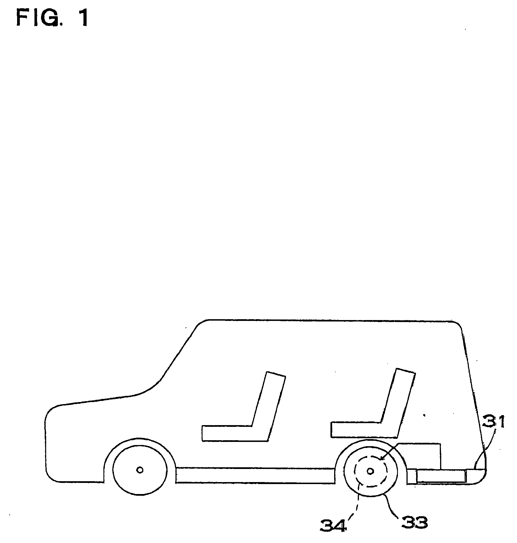
[0031] As shown in FIG. 1, a power device for a vehicle is mounted on the vehicle such as an electric car or a hybrid car. The power device is mounted on a floor panel 31 of the vehicle. A position in which the power device is to be mounted is not specified for the floor panel of the vehicle. The power device supplies a power to a motor 34 for driving a wheel 33, thereby causing the vehicle to run. The power supplied from the power device to the motor 34 is controlled by a control circuit (not shown) mounted on the vehicle. Moreover, the charge of the power device is also controlled by the control circuit. The power device of the electric car is charged by a regenerative brake when breaking is applied. The power device of the hybrid car is charged by both the regenerative brake and a generator which is mounted.

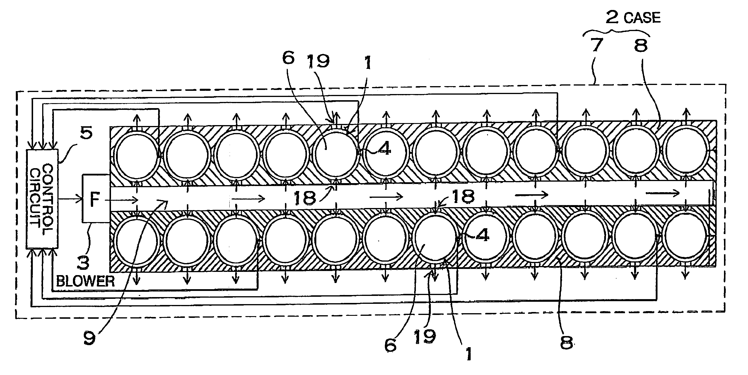
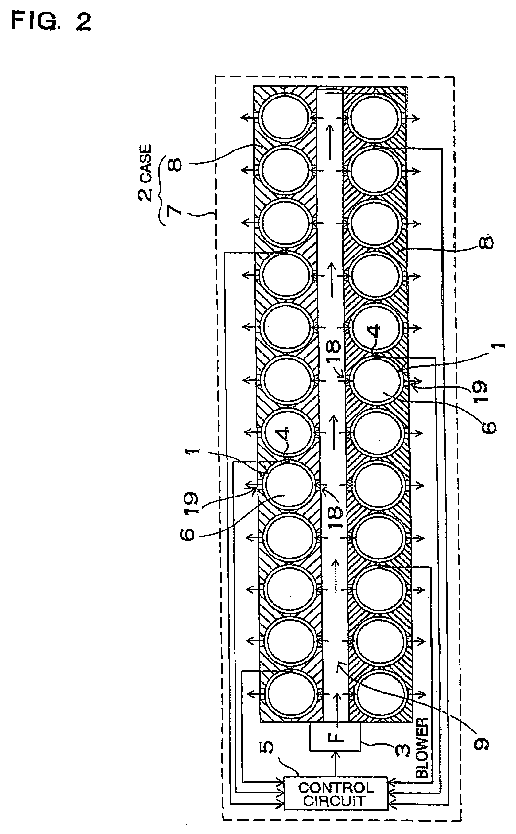
[0032]FIG. 2 is a schematic sectional view showing the power device. The power device in FIG. 2 comprises a plurality of batteries 6, a case 2 accommodating the batteries 6, ...


PUM


Abstract

A power device for a vehicle includes a plurality of batteries, a case accommodating the batteries, a blower for forcibly supplying air to the batteries accommodated in the case, thereby cooling them, and a temperature sensor for coming in contact with a surface of the battery to detect a temperature of the battery. A thermal portion for detecting the temperature of the battery of the temperature sensor includes a thermal element to be thermally coupled to the surface of the battery, and a heat insulating material having a cushioning property to be elastically compressed which serves to thermally insulate the thermal element provided on the surface of the battery from the cooling air, and the thermal element is isolated from the cooling air supplied forcibly by means of the heat insulating material having the cushioning property, thereby detecting the temperature of the battery.

Description

BACKGROUND OF THE INVENTION [0001] 1. Field of the Invention [0002] The present invention mainly relates to a power device for a large current which is to be used for a power supply of a motor for driving an automobile such as a hybrid car or an electric car. [0003] 2. Description of the Related Art [0004] An automobile such as an electric car for running by means of a motor or a hybrid car for running by means of both a motor and an engine mounts a power device accommodating a battery in a case. The power device causes the automobile to run by means of a motor. In order to increase an output, therefore, a large number of batteries are connected in series, thereby raising an output voltage and increasing the driving current of the motor. When a vehicle is to be braked, moreover, the power device is charged by regenerative braking. The regenerative braking rotates a generator by means of wheels to brake the vehicle. Therefore, the kinetic energy of the vehicle can be stored effective...

Claims


Application Information

Patent Timeline
IPC IPC(8): H02J7/04B60K1/04B60K6/28B60K11/06H01M2/10H01M10/48
CPCB60L3/0046Y02T10/7005B60L11/1877B60L11/1879H01M10/443H01M10/482H01M10/486H01M10/5004H01M10/5016H01M10/503H01M10/5059H01M10/5067H01M2200/106H02J7/0029H02J7/0091B60L11/1874H01M10/625H01M10/6563H01M10/6557H01M10/643H01M10/613B60L58/26B60L50/66B60L50/64B60L58/25B60L58/18Y02T10/70Y02E60/10H02J7/007194H02J7/00309
Inventor IZAWA, RYOSAKUTSUZURANO, NAOKI
Owner SANYO ELECTRIC CO LTD
Why Eureka
Try Eureka