Three-dimensionally vibration-preventing buffering mechanism

a buffering mechanism and three-dimensional technology, applied in the field of mechanical technology, can solve the problems of electronic system to shut down or fail to operate normally, damage to the same, and against nearby electronic components, and achieve the effect of compact size, less space occupation, and compact siz

a buffering mechanism and three-dimensional technology, applied in the field of mechanical technology, can solve the problems of electronic system to shut down or fail to operate normally, damage to the same, and against nearby electronic components, and achieve the effect of compact size, less space occupation, and compact siz

US20060029492A1Inactive Publication Date: 2006-02-09INVENTEC CORP

Image

  • Three-dimensionally vibration-preventing buffering mechanism
  • Three-dimensionally vibration-preventing buffering mechanism
  • Three-dimensionally vibration-preventing buffering mechanism

Examples


Embodiment Construction

[0019] The three-dimensionally vibration-preventing buffering mechanism according to the invention is disclosed in full details by way of several preferred embodiments in the following with reference to the accompanying drawings.

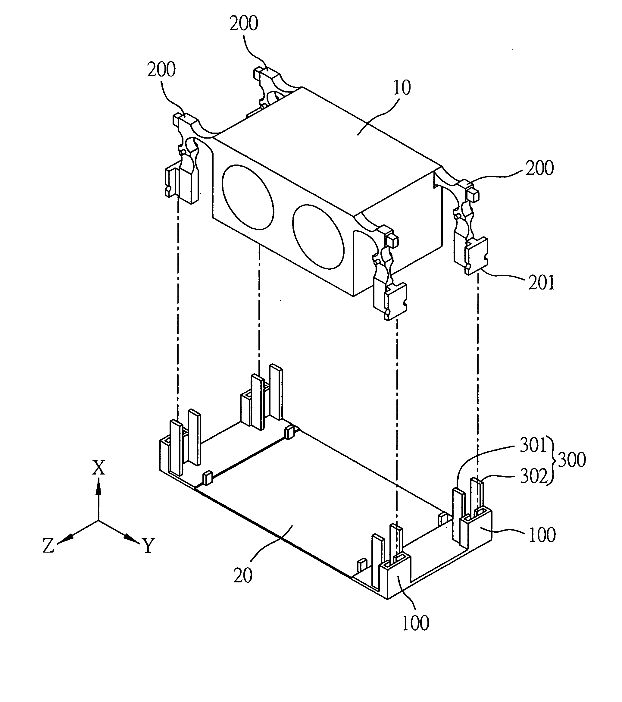
[0020]FIG. 1 is a schematic diagram showing an exploded perspective view of a first preferred embodiment of the three-dimensionally vibration-preventing buffering mechanism according to the invention, which is designed for use in conjunction with a dynamic module, such as a heat-dissipating fan unit 10 used in an electronic system (not shown), for the purpose of buffering the three-dimensional vibrations of the fan unit 10 (in reference to the three axis X, Y, Z of a three-dimensional rectangular coordinate system) during operation to prevent the fan unit 10 from being shaken violently during operation that could otherwise cause damage to nearby electronic components in the electronic system (not shown).

[0021] As shown in FIG. 1, the three-dimensionally vi...


PUM


Abstract

A three-dimensionally vibration-preventing buffering mechanism is proposed, which is designed for use in conjunction with a dynamic module for the purpose of buffering the three dimensional vibrations of the dynamic module during operation, and which is characterized by the use of a group of specially-designed chained elastic members, each being composed of at least three integrally-linked flexure hinges whose axes of concavity are oriented respectively in parallel with the three axes of a three-dimensional rectangular coordinate system, so that the vibrations of the dynamic module in all three dimensional directions can be respectively buffered by these flexure hinges to provide a three-dimensional vibration-preventing buffering effect.

Description

BACKGROUND OF THE INVENTION [0001] 1. Field of the Invention [0002] This invention relates to mechanics technology, and more particularly, to a three-dimensionally vibration-preventing buffering mechanism which is designed for use in conjunction with a dynamic module, such as a heat-dissipating fan unit used in electronic systems, for the purpose of buffering the three-dimensional vibrations of the fan unit during operation to prevent the fan unit from knocking against nearby electronic components that could otherwise cause damage to entire electronic systems. [0003] 2. Description of Related Art [0004] Electronic systems during operation typically produce large amounts of heat due to consumption of electrical power, and if this heat is undissipated, it would result in burnout of electrical components or chips (such as CPUs), thus causing the electronic system to shut down or fail to operate normally. One solution to this problem is to mount heat-dissipating devices, such as electri...

Claims


Application Information

Patent Timeline
09 Feb 2006
Publication
US20060029492A1
IPC
F04D29/66
CPC
F04D29/601; F16F2230/34; F16F15/04; F04D29/668
Inventors
KAO, CHENG-SHEN