Non-line-of-sight process for coating complexed shaped structures

a technology of complexes and coatings, applied in the direction of liquid/fluent solid measurements, peptides, machines/engines, etc., can solve the problems of difficult coating by line-of-sight processes and difficult physical deposition techniques for coatings

Active Publication Date: 2006-02-09
RAYTHEON TECH CORP
View PDF6 Cites 56 Cited by
  • Summary
  • Abstract
  • Description
  • Claims
  • Application Information

AI Technical Summary

Benefits of technology

[0009] The present invention relates to processes for the deposition of protective coatings on complex shaped substrates, and particularly Si-based substrates, which are used in articles and structures subjected to high temperature, aqueous environments. Other substrates are contemplated in addition to Si-based substrates and include metal, all

Problems solved by technology

By complex shaped is meant components which have geometric shapes which make physical deposition

Method used


Image

  • Non-line-of-sight process for coating complexed shaped structures
  • Non-line-of-sight process for coating complexed shaped structures

Examples


Embodiment Construction

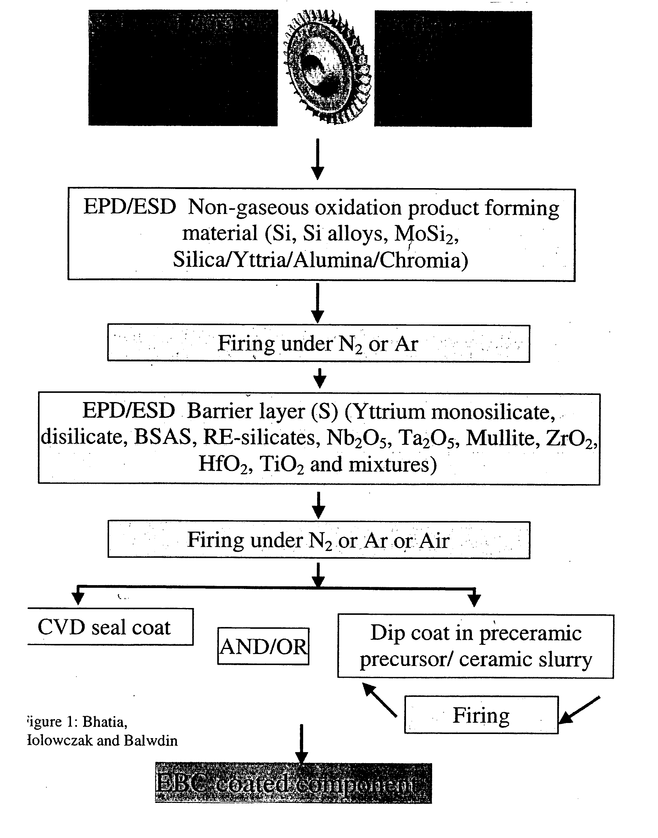
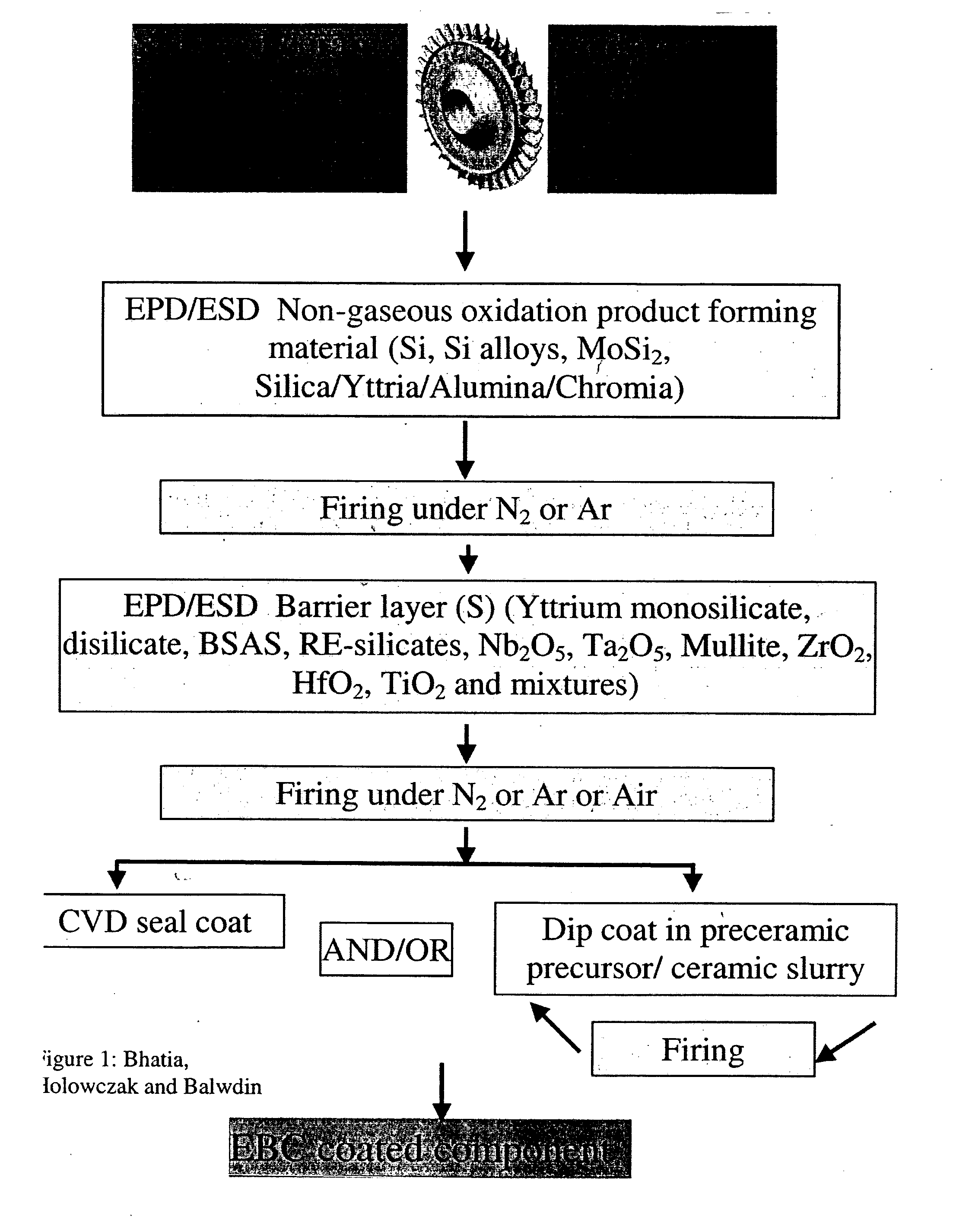
[0014] The present invention relates to a process for the deposition of protective coatings on complex shaped Si-based substrates which are used in structures subjected to high temperature, aqueous environments. By complex shaped parts that require protective coatings are meant components typically airfoils or narrow tubular gas turbine components, that are difficult (if not impossible) to coat efficiently by line-of-sight processes. The geometry of the component makes it difficult to access it by either a plasma gun or by gaseous precursor species in conventional physical deposition techniques. An example of a complex shaped part is an integral vane assembly which consists of a set of 8-20 vanes with integral outer and inner platforms. It could also apply to airfoil doublets. Internal turbine blade assemblies that require coatings are also considered complex shaped components. Typically, when such components are coated by line-of-sight techniques such as thermal spray and physical ...


PUM

PropertyMeasurementUnit
Temperatureaaaaaaaaaa
Fractionaaaaaaaaaa
Timeaaaaaaaaaa

Abstract

Non-line-of-sight process for coating complexed shaped structures of Si-based substrates with protective barrier layers.

Description

U.S. GOVERNMENT RIGHTS [0001] The invention was made with U.S. Government support under contract N00014-01-C-0032 awarded by the U.S. Navy. The U.S. Government may have certain rights in the invention.BACKGROUND OF THE INVENTION [0002] The present invention relates to a process for the deposition of protective coatings on complex shaped Si-based substrates which are used in articles subjected to high temperature, aqueous environments. [0003] Ceramic materials containing silicon have been proposed for structures used in high temperature applications, for example, gas turbine engines, heat exchangers, internal combustion engines, and the like. A particularly useful application for these materials is in gas turbine engines, which operate at high temperatures in aqueous environments. It has been found that such silicon containing substrates can recede and lose mass as a result of a formation volatile Si species, particularly Si(OH)x and SiO when exposed to high temperature, aqueous envi...

Claims


Application Information

Patent Timeline
IPC IPC(8): C23C16/00B05D1/36B01D57/02
CPCC04B41/009F05D2230/30C04B41/89C23C24/00C23C24/08C23C26/00C25D13/22F01D5/288C04B41/52F05D2300/222F05D2300/611F05D2230/90C04B41/4529C04B41/5096C04B41/51C04B41/522C04B41/0072C04B41/4517C04B41/4564C04B41/5024C04B41/4568C04B41/5027C04B41/4531C04B35/565C04B35/584
Inventor BHATIA, TANIABALDWIN, NEILBARTH, ROBERT A.TANG, XIAHOLOWCZAK, JOHN E.
Owner RAYTHEON TECH CORP
Why Eureka
Try Eureka