Pedicle screw and operating device thereof

a technology of pedicle screw and operating device, which is applied in the field of spine fixation apparatus, can solve the problems of difficult to determine the coupling position of the screw section of the pedicle screw, failure of surgery operation, and operator's inability to see the pedicle screw

Active Publication Date: 2006-02-09
SOLCO BIOMEDICAL +1
View PDF10 Cites 142 Cited by
  • Summary
  • Abstract
  • Description
  • Claims
  • Application Information

AI Technical Summary

Benefits of technology

[0018] Accordingly, the present invention has been made to solve the above-mentioned problems occurring in the prior art, and an object of the present invention is to provide a pedicle screw including a support unit, which connects a first sidewall of a head section to a second sidewall of the head section in order to prevent a rod, which is inserted into the head section of the pedicle screw from a lateral portion of the pedicle screw, from being separated upward from the head section.
[0019] Another object of the present invention is to provide a pedicle screw including an indicator protruding from an end of a screw section of the pedicle screw for precisely indicating an insertion point of the pedicle screw during minimum incision surgery.
[0020] Still another object of the present invention is to provide an operating device for a pedicle screw allowing an operator to easily perform minimum incision surgery while making several incisions for the pedicle screw and a rod in the back of a patient.

Problems solved by technology

For this reason, if the conventional pedicle screw is used for the minimum incision surgery, the pedicle screw may be separated from the pedicle screw while the surgery operation is being carried out, resulting a delay or a failure of the surgery operation.
Thus, it is difficult to determine a coupling position of a screw section of the pedicle screw having a diameter of about 5 mm with respect to the spine of the patient.
This is because the incisions made in the back of the patient tend to be clogged by skin and the operator cannot see the pedicle screw, which has already been implanted in the body of the patient.
That is, since the minimum incision surgery is carried out while making several incisions in the back of the patient and keeping the size of the incisions quite small, the location of the pedicle screw is “subcutaneous”, so that the operator cannot easily carry out minimum incision surgery.

Method used


Image

  • Pedicle screw and operating device thereof
  • Pedicle screw and operating device thereof
  • Pedicle screw and operating device thereof

Examples


Embodiment Construction

[0041] Hereinafter, a preferred embodiment of the present invention will be described with reference to the accompanying drawings.

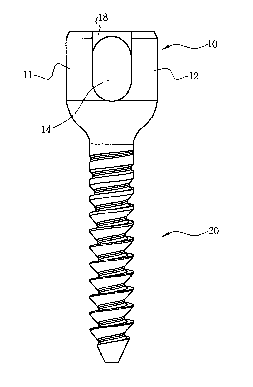
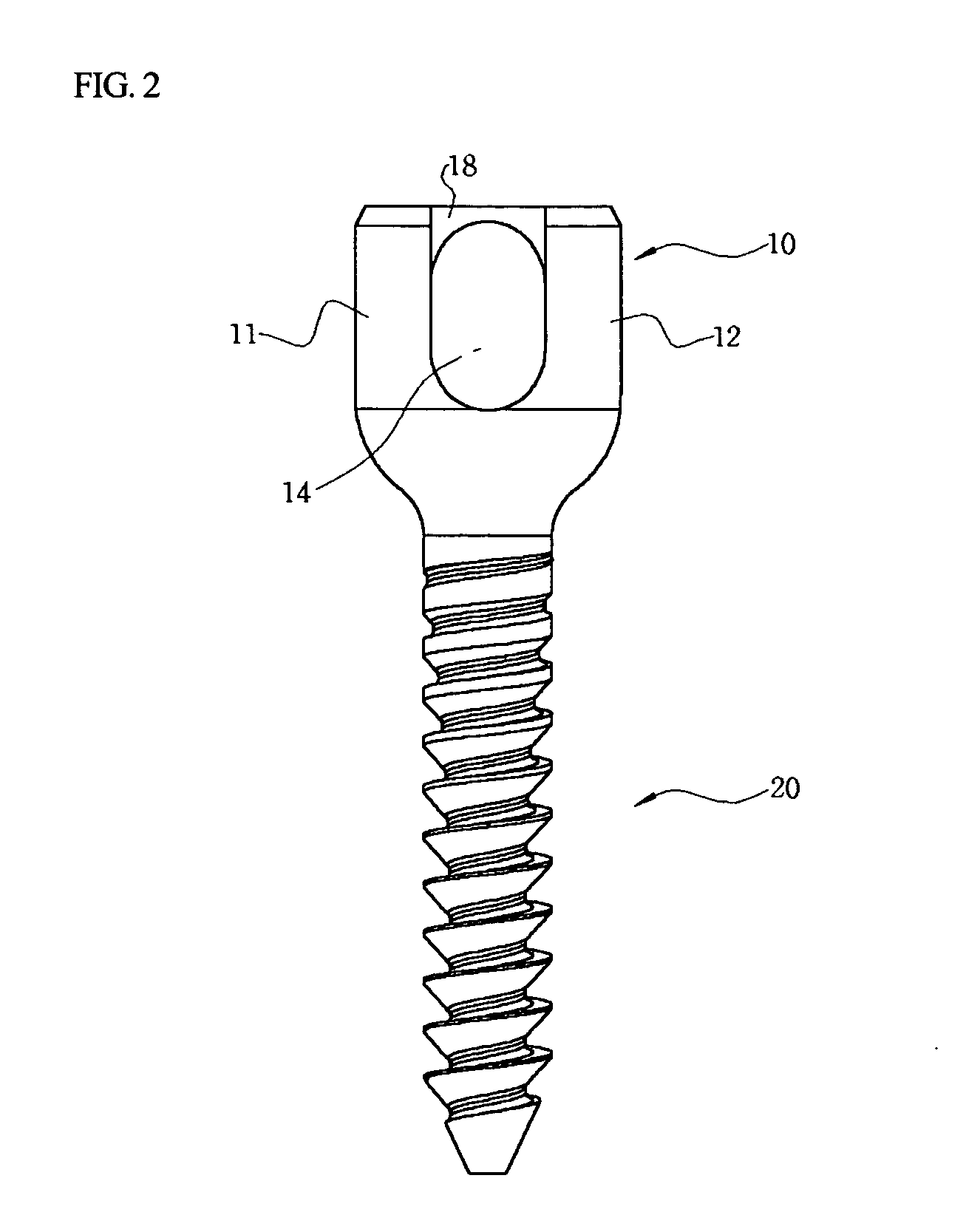
[0042] FIGS. 2 to 4 are front, plan and perspective views of a pedicle screw according to one embodiment of the present invention Referring to FIGS. 2 to 4, the pedicle screw includes a head section 10 formed with first and second sidewalls 11 and 12. A recess 14 is formed between the first and second sidewalls 11 and 12 and a support unit 18 is formed at an upper portion of the recess 14 in order to connect the first sidewall 11 to the second sidewall 12.

[0043] The support unit 18 horizontally connects upper portions of the first and second sidewalls 11 and 12 to each other. Thus, the support unit 18 forms a hole having a predetermined size together with the recess 14. The shape and position of the support unit 18 may vary so far as the support unit 18 connects the first sidewall 11 to the second sidewall 12 and prevents a rod (not shown) from being se...


PUM


Abstract

Disclosed is a spine fixation apparatus, more particularly, a pedicle screw implanted into a spine and an operating device for the pedicle screw capable of easily inserting a rod to a head section of the pedicle screw in order to securely fix the spine. The pedicle screw has a head section including a recess part defined by first and second sidewalls, a screw section, and a support unit formed at an upper portion of the recess part of the head section while connecting the first sidewall to the second sidewall. The operating device has a screw coupling rod having an elongated pipe shape, a body having a first side coupled to the screw coupling rod, a rotating member having a first end coupled to a second side of the body in such a manner that a second end of the rotating member rotates about the first end thereof, and a rod receiver coupled to the second end of the rotating member. Due to the support unit, the rod is prevented from being easily separated from the pedicle screw, thereby facilitating minimum incision surgery. The operating device for the pedicle screw allows an operator to easily perform minimum incision surgery while making several incisions for the pedicle screws and the rod in the back of the patient and keeping the size of incisions quite a small.

Description

BACKGROUND OF THE INVENTION [0001] 1. Field of the Invention [0002] The present invention relates to a spine fixation apparatus, and more particularly to a pedicle screw implanted into a spine and an operating device for the pedicle screw capable of easily inserting a rod to a head section of the pedicle screw in order to securely fix the spine. [0003] 2. Description of the Prior Art [0004] As generally known in the art, a spine fixation apparatus is provided for treating patients who have vertebral disease caused by traffic accidents or fall accidents. For instance, the spine fixation apparatus connects bones forming the spine to each other so as to assist patients with vertebral fracture to be restored to health. [0005] A patient makes a living with a spine fixation apparatus implanted into the spine of the patient. Thus, a subsidiary implanted into a body of the patient must have a simple structure and must not be deformed or released even if the patient takes an active life for ...

Claims


Application Information

Patent Timeline
Patent Type & Authority Applications(United States)
IPC IPC(8): A61B17/00
CPCA61B17/7032A61B17/864A61B17/7089
Inventor PARK, KEUN HOCHOI, JONG MYEONLEE, HOON
Owner SOLCO BIOMEDICAL
Why Eureka
Try Eureka