Apparatuses and methods for heart valve repair

a heart valve and apparatus technology, applied in the field of medical devices, can solve the problems of heart damage, long recovery time and hospitalization time, patients to a lot of pain and discomfort, etc., and achieve the effect of restricting or reducing the size of the faulty heart valv

Inactive Publication Date: 2006-02-09
HYDE GREGORY MATHEW
View PDF99 Cites 522 Cited by
  • Summary
  • Abstract
  • Description
  • Claims
  • Application Information

AI Technical Summary

Benefits of technology

[0012] In one exemplary embodiment of the present invention, a medical device comprises a ligature, including a first anchoring member and a second anchoring member. The ligature is used to treat a hear having a faulty heart valve (e.g., a faulty mitral valve). The ligature is percutaneously dep...

Problems solved by technology

A normal mitral valve allows blood to flow into the left ventricle and does not allow leaking or regurgitating back into the left atrium and then into the lungs.
The aortic valve allows blood to flow into the aorta and does not allow leaking (or regurgitating) back into the left ventricle.
The heart then has to work harder to pump e...

Method used


Image

  • Apparatuses and methods for heart valve repair
  • Apparatuses and methods for heart valve repair
  • Apparatuses and methods for heart valve repair

Examples


Embodiment Construction

[0042] The present invention pertains to novel medical devices and methods of using these medical devices to treat defective or faulty heart valves. In the following description, for purposes of explanation, numerous specific details are set forth in order to provide a thorough understanding of the present invention. It will be evident, however, to one skilled in the art, that the present invention may be practiced without these specific details. In other instances, specific apparatus structures and methods have not been described so as not to obscure the present invention. The following description and drawings are illustrative of the invention and are not to be construed as limiting the invention.

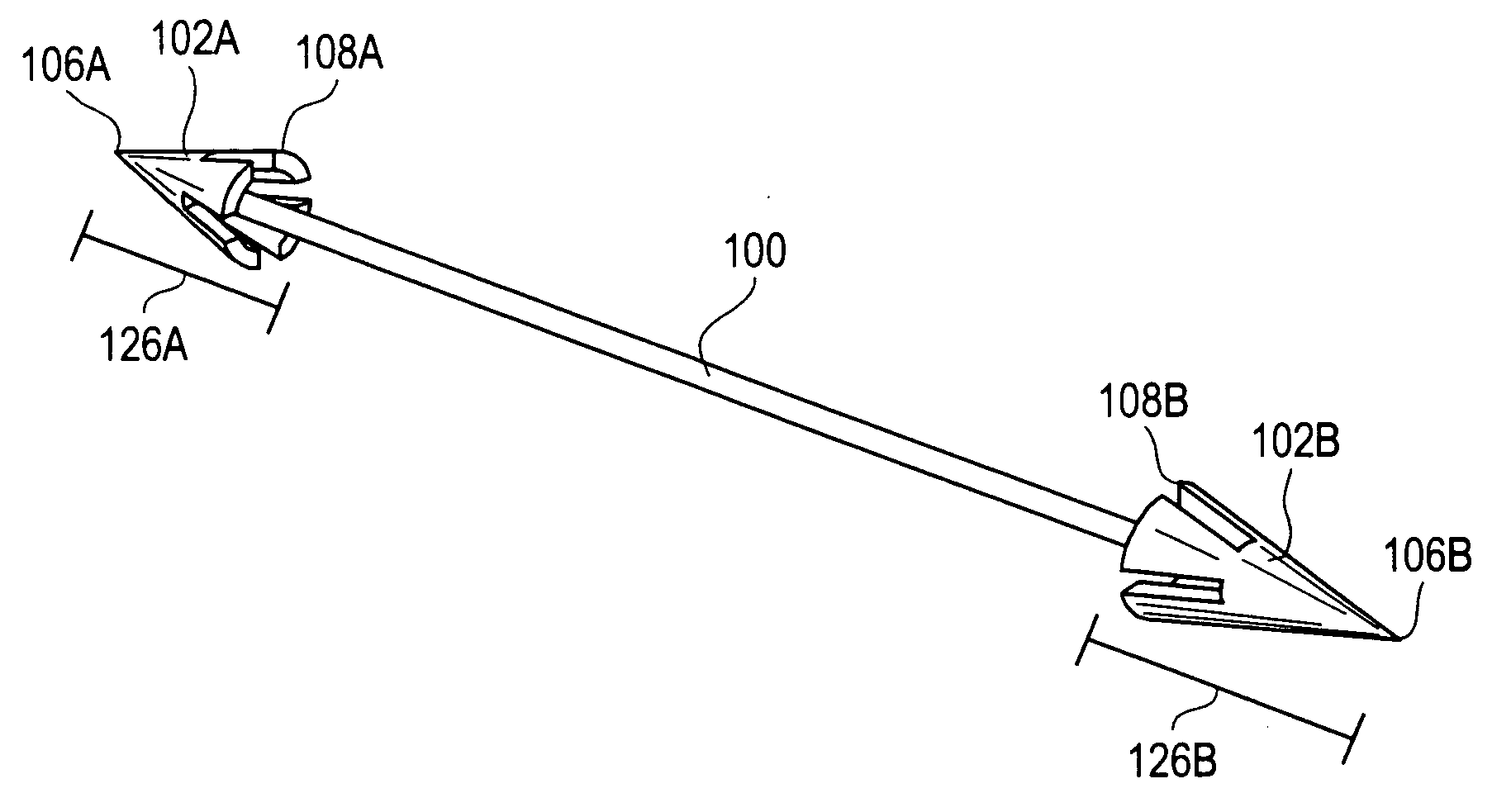
[0043]FIG. 2A illustrates an exemplary embodiment of a medical device that comprises a ligature 100. The ligature 100 can be a strap, string, cord, wire, bond, thread, suture, or other connector. The ligature 100 includes a first anchoring member 102A and a second anchoring member 102B. ...


PUM


Abstract

A medical device for treating a heart having a faulty heart valve is disclosed. The medical device comprises a ligature including a first anchoring member and a second anchoring member is used. The ligature is percutaneously deployable into a patient with a faulty heart valve wherein the first anchoring member to anchor to a first tissue area of the heart and the second anchoring member to anchor to a second tissue area of the heart.

Description

BACKGROUND OF THE INVENTION [0001] 1. Field of the Invention [0002] The present invention involves a medical device that is used for treating a defective heart valve. [0003] 2. Discussion of Related Art [0004]FIG. 1A illustrates a heart 10. There are four valves in the heart 10 that serve to direct the flow of blood through the two sides of the heart 10 in a forward direction. The four valves are a mitral valve 20, an aortic valve 18, a tricuspid valve 60, and a pulmonary valve 62 as illustrated in FIG. 1A. The mitral valve 20 is located between the left atrium 12 and the left ventricle 14. The aortic valve 18 is located between the left ventricle 14 and the aorta 16. These two valves direct oxygenated blood coming from the lungs, through the left side of the heart, into the aorta 16 for distribution to the body. The tricuspid valve 60 is located between the right atrium 22 and the right ventricle 24. The pulmonary valve 62 is located between the right ventricle 24 and the pulmonary...

Claims


Application Information

Patent Timeline
IPC IPC(8): A61B17/04
CPCA61B17/00234A61B17/068A61B17/0483A61B17/06061A61B2017/00243A61B2017/00783A61B2017/0409A61B2017/0441A61B2017/0472A61B2017/0475A61B2017/0496A61B2017/06057A61B2017/0649A61F2/2445A61F2/2454A61F2/2487A61B17/0401
Inventor HYDE, GREGORY MATHEW
Owner HYDE GREGORY MATHEW
Why Eureka
Try Eureka