Exhaust gas recirculation valve

a technology of exhaust gas and recirculation valve, which is applied in the direction of mechanical equipment, machines/engines, and fuel addition of non-fuel substances, etc., and can solve the problems of stick or restrict movement, and unsatisfactory requirements

Active Publication Date: 2006-02-16
BORGWARNER INC
View PDF24 Cites 22 Cited by
  • Summary
  • Abstract
  • Description
  • Claims
  • Application Information

AI Technical Summary

Problems solved by technology

Pneumatically actuated valves depend upon the availability of pressure or vacuum on the vehicle and this may be an undesirable requirement.
Components in the exhaust gas can accumulate on the valve components and cause them to stick or restrict movement if sufficient operating force is not available.
By way of a non-limiting example, during normal operation of diesel engines, especially those employing cooled EGR systems, the EGR valve poppet often becomes stuck to the valve seat in the closed position, due to excessive build up of various exhaust gas components, which renders the valve inoperable.

Method used


Image

  • Exhaust gas recirculation valve
  • Exhaust gas recirculation valve
  • Exhaust gas recirculation valve

Examples


Embodiment Construction

[0031] The following description of the preferred embodiment(s) is merely exemplary in nature and is in no way intended to limit the invention, its application, or uses.

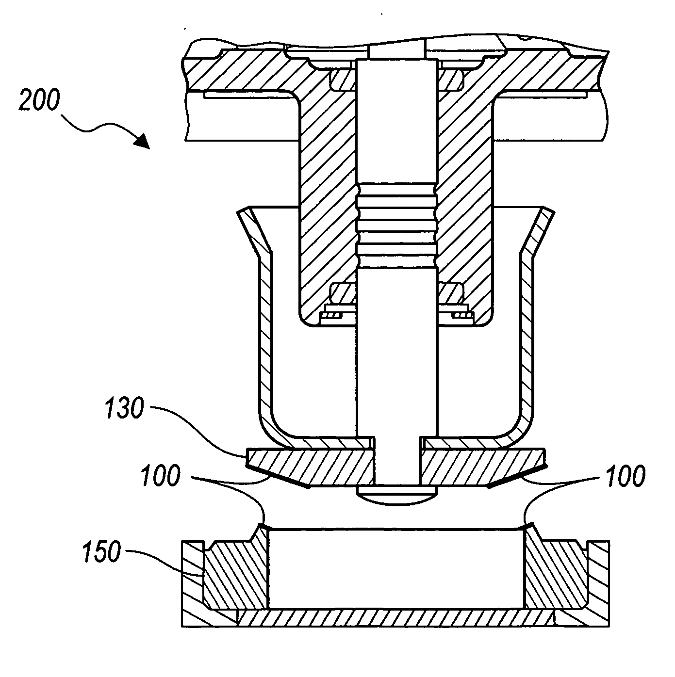
[0032] In accordance with the general teachings of the present invention, an anti-stick medium is applied to an external surface of a member that contacts, regardless of orientation, action, or purpose, another member. The intended function of the anti-stick medium is to prevent the adherence, accumulation, bonding, and / or sticking of any contaminants (e.g., lacquer) or other undesirable materials contained or entrained in a fluid (e.g., exhaust gas) on the surfaces that have been coated with the anti-stick medium.

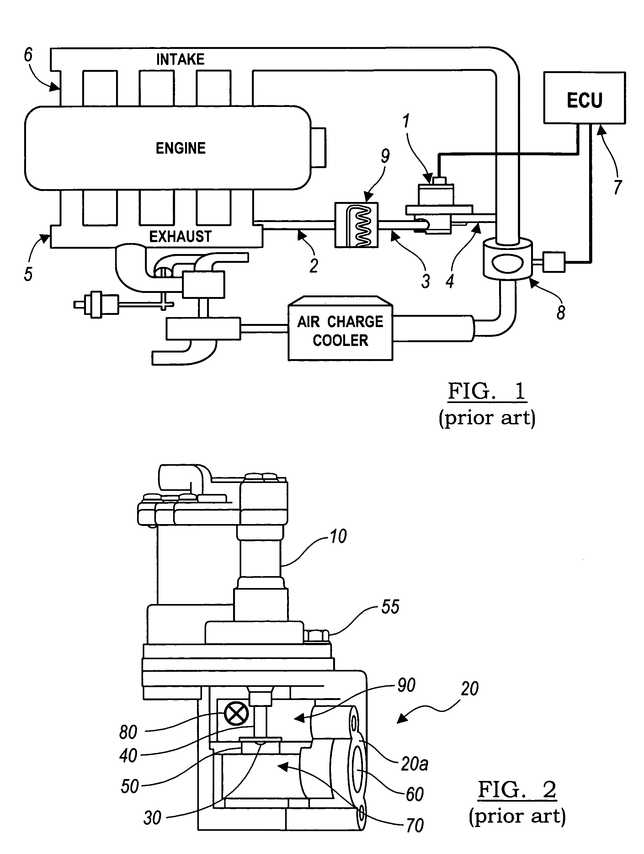
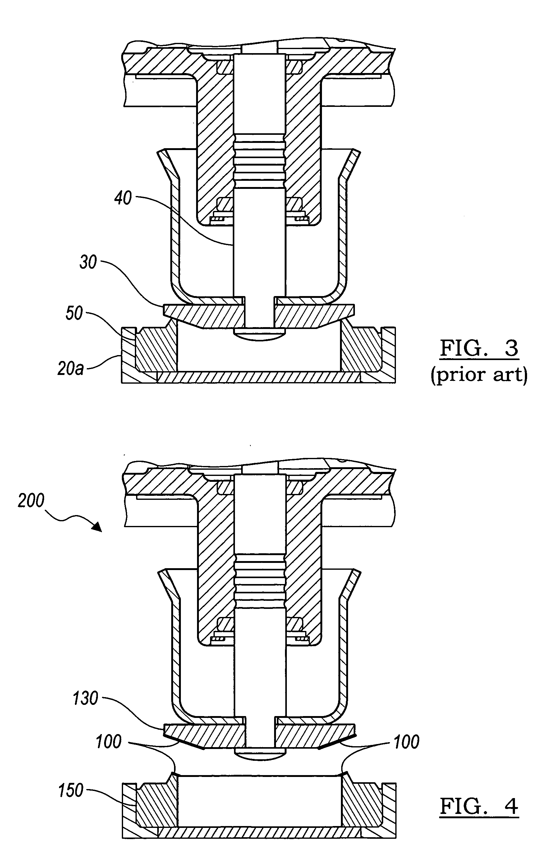
[0033] By way of a non-limiting example, an EGR valve system is provided, wherein an anti-stick medium is applied to the EGR valve components such as, but not limited to: (a) the valve (e.g., a poppet); (b) the valve seat; or (c) the valve and valve seat together. The present invention is particularly sui...


PUM


Abstract

Mechanical systems having anti-stick mediums applied thereto are provided. In one aspect, exhaust gas recirculation (EGR) valve systems having anti-stick mediums applied thereto are also provided. The anti-stick medium can be applied to any contacting surface, such as but not limited to the valve surface and / or the valve seat surface. The anti-stick medium is intended to prevent the valve surface and the valve seat surface sticking or bonding together, especially with respect to the operation of cooled or cold side EGR systems. If any materials should stick to the anti-stick medium, a portion of the anti-stick medium will break away from the surface, allowing the surface and / or component to function normally. The anti-stick medium can include, without limitation, boron nitride coatings, boron nitride aerosols, boron nitride greases, thin dense chrome platings, perfluoroalkoxy, and combinations thereof.

Description

CROSS-REFERENCE TO RELATED APPLICATION [0001] The instant application claims priority to U.S. Provisional Patent Application Ser. No. 60 / 600,844, filed Aug. 12, 2004, the entire specification of which is expressly incorporated herein by reference.FIELD OF THE INVENTION [0002] The present invention generally relates to exhaust gas recirculation valves, and more particularly to exhaust gas recirculation valve systems that include an anti-stick medium applied to either the valve poppet surface and / or the valve seat surface. BACKGROUND OF THE INVENTION [0003] Current Federal and State legislation generally requires control of vehicle exhaust emissions. Oxides of Nitrogen (“NOx”) are one of the exhaust gas emissions that must be controlled. Formation of NOx typically occurs at higher combustion temperatures. A system, generally referred to as the exhaust gas recirculation (“EGR”) system, has been developed to reduce peak combustion temperatures that reduce NOx emissions. An illustrative ...

Claims


Application Information

Patent Timeline
Patent Type & Authority Applications(United States)
IPC IPC(8): F02M25/07
CPCF02M25/0701F02M25/0707F02M25/0714Y02T10/121F02M25/0789F02M25/079F02M25/0797F02M25/0772F02M26/05F02M26/11F02M26/50F02M26/53F02M26/67F02M26/68F02M26/74
Inventor WILSON, JOSEPH A.HOPKINS, MICHEAL JR.MCINTYRE, JAMES T.ABBITT, GUY L.CZARNOWSKI, ROBERT S.
Owner BORGWARNER INC
Why Eureka
Try Eureka