Adjustable feed tube

a feed tube and adjustable technology, applied in the field of feed tubes, can solve the problems of not being able to meet the universally accepted standard for the outside diameter of the hopper neck, non-adjustable feed tubes often do not properly secure the hopper, and the hopper may not be properly secured to the paintball gun, etc., to achieve convenient operation, easy adjustment, and easy clamping

a feed tube and adjustable technology, applied in the field of feed tubes, can solve the problems of not being able to meet the universally accepted standard for the outside diameter of the hopper neck, non-adjustable feed tubes often do not properly secure the hopper, and the hopper may not be properly secured to the paintball gun, etc., to achieve convenient operation, easy adjustment, and easy clamping

US20060032488A1Active Publication Date: 2006-02-16KEE ACTION SPORTS I +2

Image

  • Adjustable feed tube
  • Adjustable feed tube
  • Adjustable feed tube

Examples


Embodiment Construction

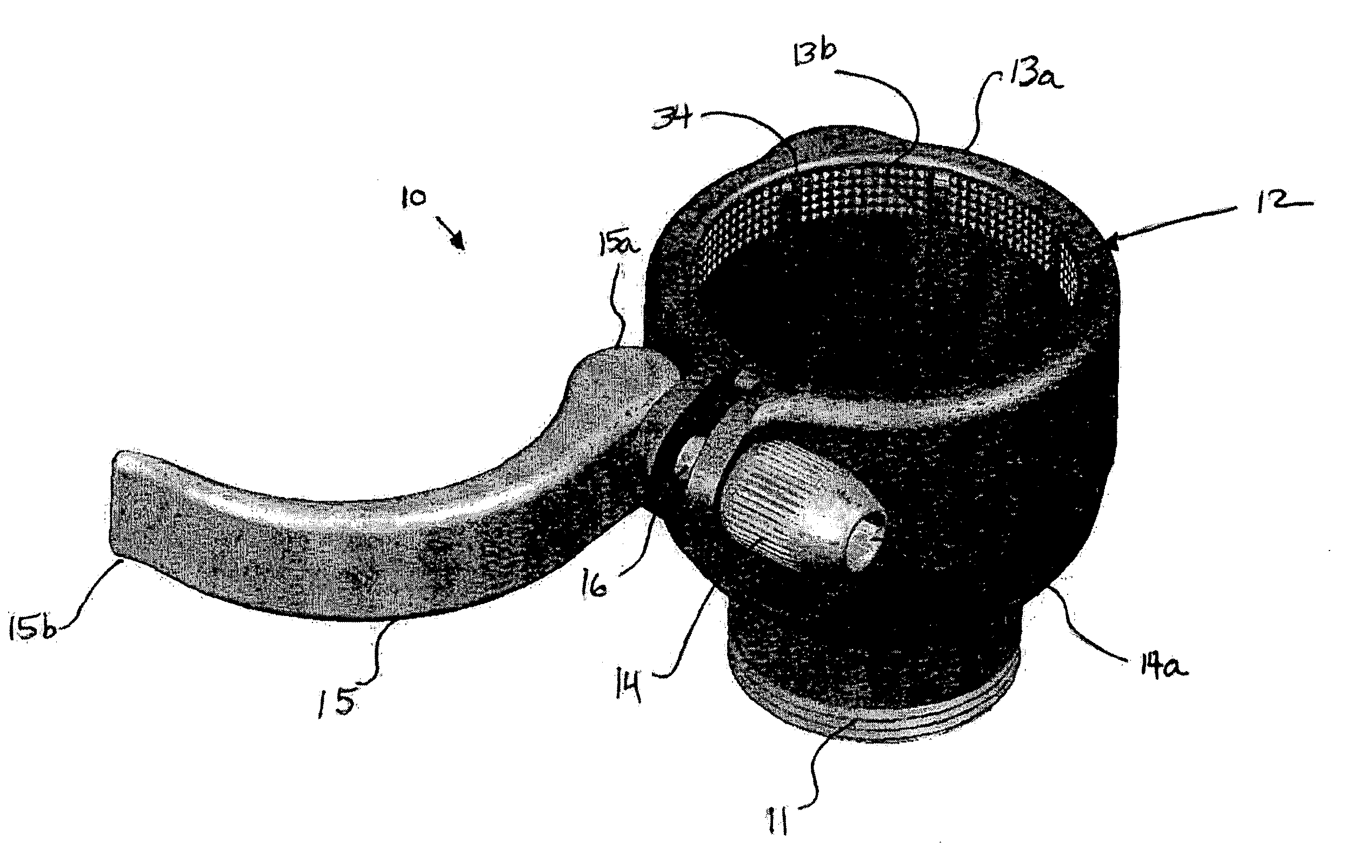
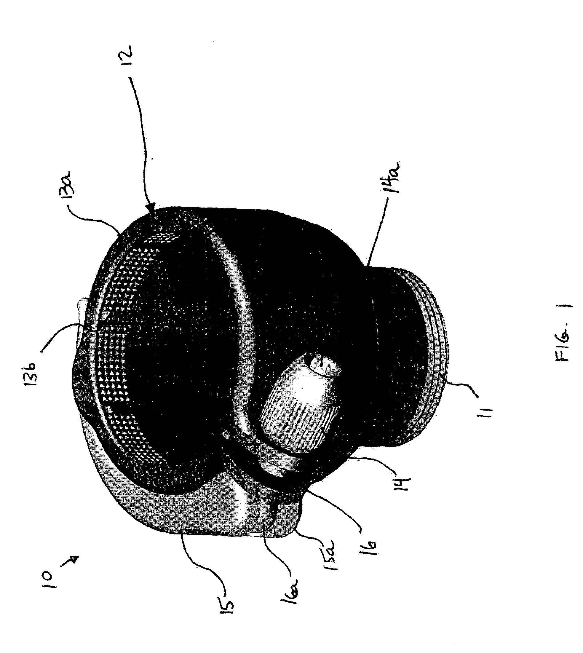
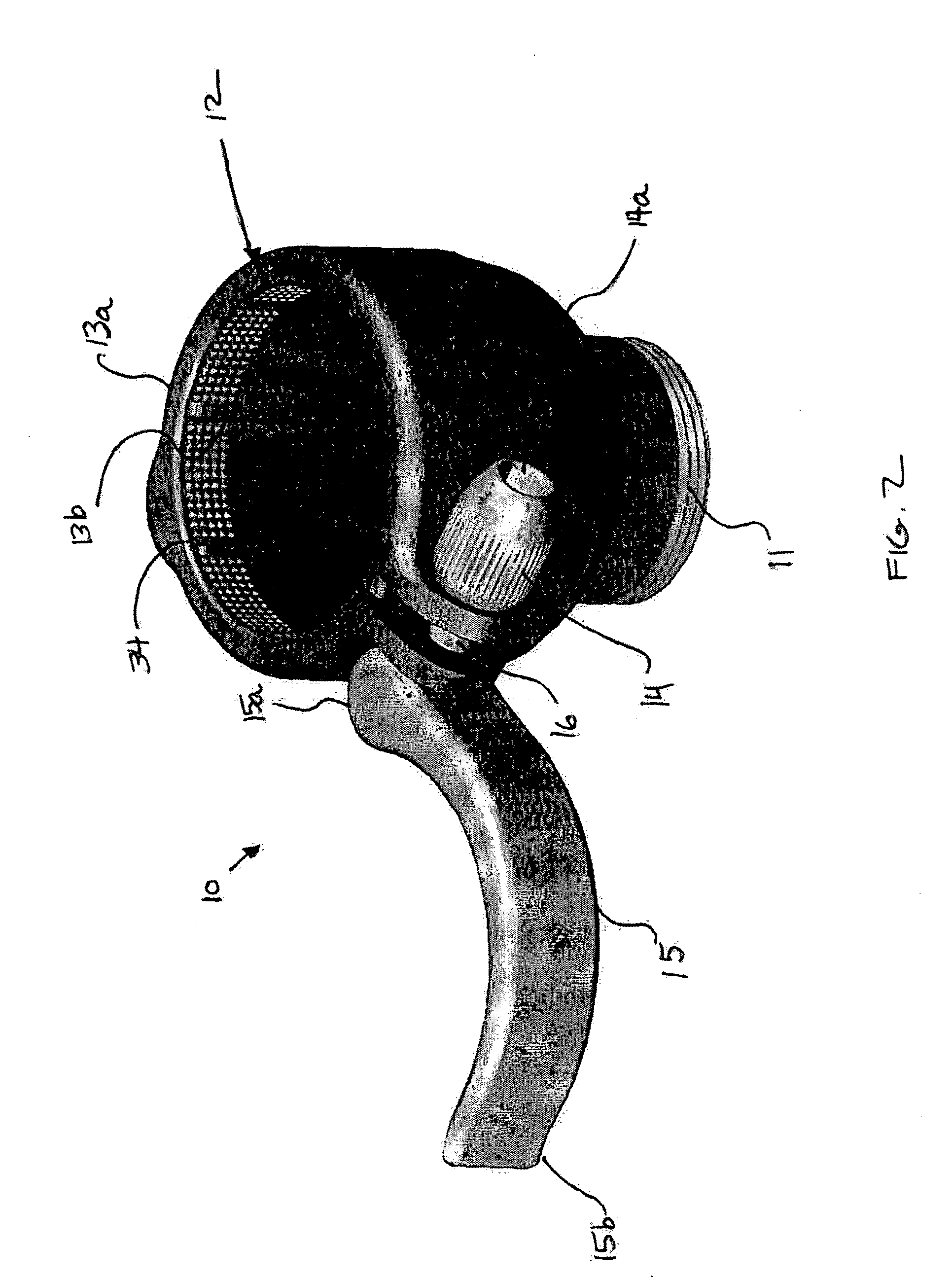
[0025]FIG. 1 is a perspective view of an adjustable, clamping feed tube 10 according to a preferred embodiment of the present invention, showing a clamp 13a in the closed position. FIG. 2 is a perspective view of the adjustable, clamping feed tube 10 of FIG. 1, showing the clamp 13a in an open position. FIGS. 3-5 are various views of the feed tube 10 of FIG. 1, illustrating the clamp 13a in both open and closed positions. FIGS. 6-10 are perspective views of various components of the adjustable, clamping feed tube 10 of FIG. 1, giving a more detailed understanding of various principles of the present invention.

[0026] Referring to FIGS. 1-10, the adjustable, clamping feed tube 10 includes a threaded portion 11 that provides a threaded engagement with a paintball gun (not shown). A receiving end 12 is located opposite the threaded portion 11 to receive a hopper neck (not shown). An opening in the receiving end 12 can be quickly enlarged by opening a clamping member 13a. The clamp 13a ...


PUM


Abstract

A paintball gun preferably includes an adjustable, clamping feed tube. The feed tube can, for instance, include a lever for closing and opening a clamp, thereby tightening or loosening a receiving end of a feed tube to secure or release a hopper neck. The feed tube also preferably includes a finger adjustable nut for adjusting the size of the receiving end to accommodate differently sized hopper necks.

Description

BACKGROUND OF THE INVENTION [0001] 1. Field of the Invention [0002] The present invention relates generally to feed tubes for connecting paintball hoppers (or loaders) to a paintball gun, and more particularly to adjustable and clamping feed tubes for paintball guns. [0003] 2. Description of Related Art [0004] Conventional feed tubes are typically attached to a paintball gun by screwing a threaded portion of the feed tube into a receiving hole arranged near the breech end of the paint ball gun. Feed tubes provide a connection between a paintball hopper (or loader) and the paintball gun to permit paintballs from the hopper to feed into the breech of the paintball gun for launching. Hoppers typically include a storage chamber, a lid, and a neck. The neck is typically a hollow tube that fits into a receiving end of the feed tube, located opposite the threaded portion of the feed tube. The hollow portion of the hopper neck must be large enough to accommodate a paintball, which is typica...

Claims


Application Information

Patent Timeline
16 Feb 2006
Publication
US20060032488A1
IPC
F41F1/00
CPC
F41B11/52
Inventors
TELFORD, EDWARD S.