Heating plate for vacuum filter press

a vacuum filter press and heating plate technology, applied in the field of filter presses, can solve the problems of increasing the overall size (i.e., length), the space requirements and the cost of the press, and the addition of moisture to the filter cak

Inactive Publication Date: 2006-02-16
UNITED STATES FILTER CORPORATION
View PDF14 Cites 32 Cited by
  • Summary
  • Abstract
  • Description
  • Claims
  • Application Information

AI Technical Summary

Benefits of technology

[0012] In the improved filter press of the present invention, the press is defined by a closable stack of filter plates defined by a first plurality of membrane filter plates which are alternately disposed with a second plurality of heating-type filter plates. The membrane plates, as is conventional, have chamber-defining recesses on opposite sides thereof, with each recess having a flexible membrane associated therewith which can be pressurized from the rearward side so as to effect squeezing of the cake in the filtration chamber. Each heating plate also has chamber-defining recesses on opposite sides thereof, and the main center bottom wall of each recess has a metal heat transfer surface associated therewith, the rear side of which is in intimate contact with a chamber or passage which receives therein a high-temperature heat transfer fluid.

Problems solved by technology

This also effects limited heating of the filter cake which, in conjunction with a vacuum applied to the discharge side of the filter cloths, causes additional moisture to be removed from the filter cake.
While filter presses employing membrane-type filter plates have provided improvement with respect to removal of liquid from the filter cake, nevertheless such membrane-type filter plates are of limited capability with respect to their ability to provide effective heating of the filter cake to assist in moisture removal by vaporization.
With a filter press employing alternating metal heating plates of the type described above, however, the overall construction of the filter press, in order to maintain the same press capacity, increases significantly with respect to the structure and size thereof since the same number of membrane-type filter plates must be maintained, and at the same time a substantially similar number of heating plates are incorporated into the press, thereby significantly increasing the overall size (i.e., length) and also the space requirements and cost of the press.
In addition, in a press having alternating membrane-type and metal heating plates as mentioned above, the heating plates are constructed substantially entirely of metal and function solely to provide heat to the filter cake, but are not designed to cooperate with or promote other required or desired operational features of the press.
This restricts the ability of the press to effect efficient drainage of liquid from the filtration chamber.
This also restricts the effective use of air blow into and through the filter cake to further assist in vapor removal since the only ports available for air blow are provided on one side of the filtration chamber, namely in the membrane filter plate, and as such the air blow can effect movement of air only transversely across the filter cake and not longitudinally through the thickness thereof, whereby the effectiveness of the air blow is believed significantly impaired.

Method used


Image

  • Heating plate for vacuum filter press
  • Heating plate for vacuum filter press
  • Heating plate for vacuum filter press

Examples


Embodiment Construction

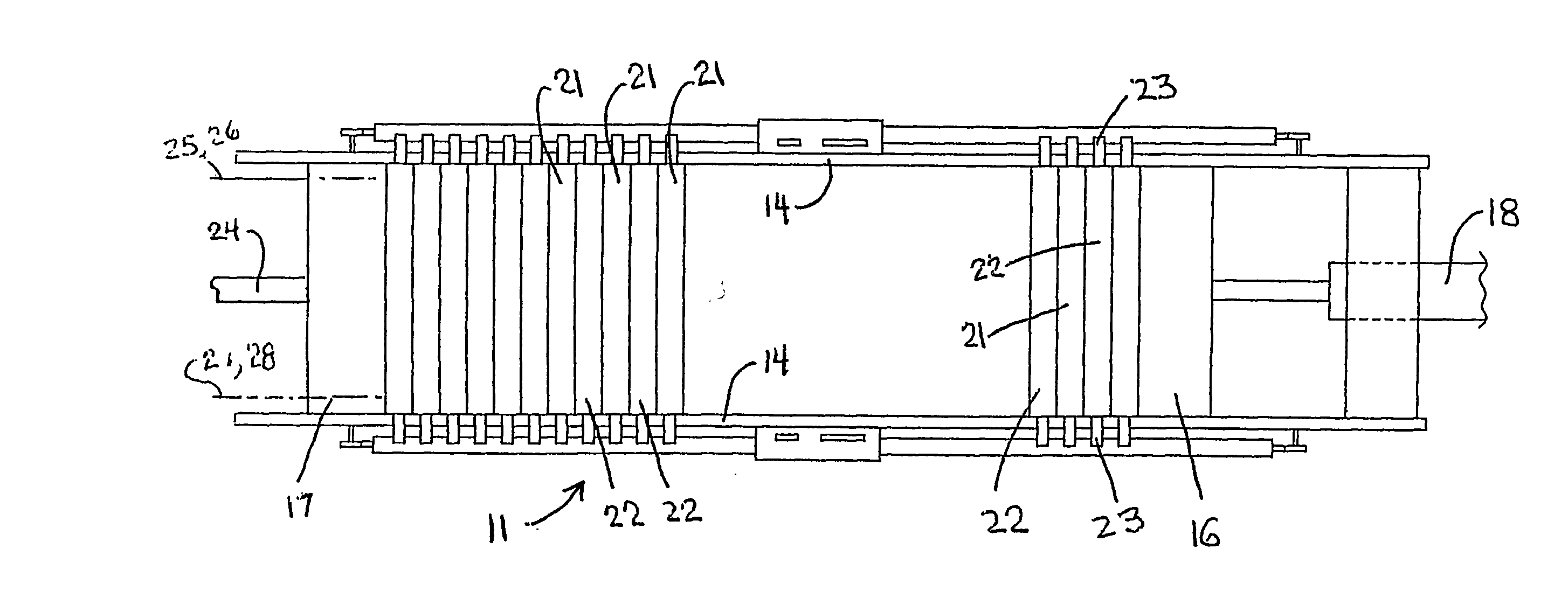
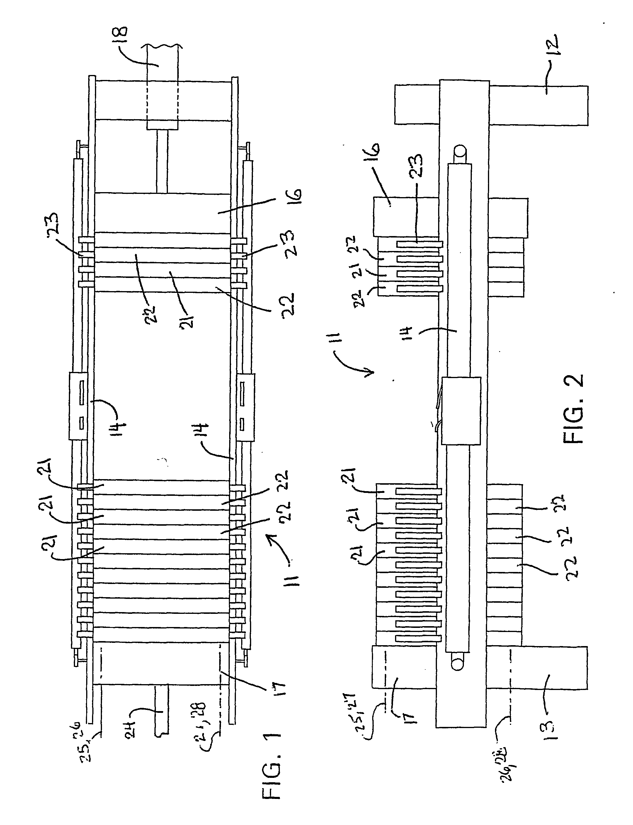
[0034] As shown in FIGS. 1 and 2, there is illustrated a filter press 11 having a pair of end supports 12 and 13 rigidly joined by a pair of generally parallel and horizontally elongate side rails 14, which side rails are sidewardly spaced apart and cooperate with the end supports 12 and 13 to define a generally rigid frame.

[0035] The filter press 11 has a movable follower or head arrangement 16 disposed adjacent one end of the press frame and slidably supported for movement along the side rails 14. The movable head 16 is slidably displaceable horizontally along the side rails toward and away from a further head 17 which is fixed to the frame adjacent the other end thereof. A drive device 18, such as a conventional double acting pressure cylinder, is mounted on the frame and cooperates with the movable head 16 for controlling movement thereof either toward or away from the fixed head 17.

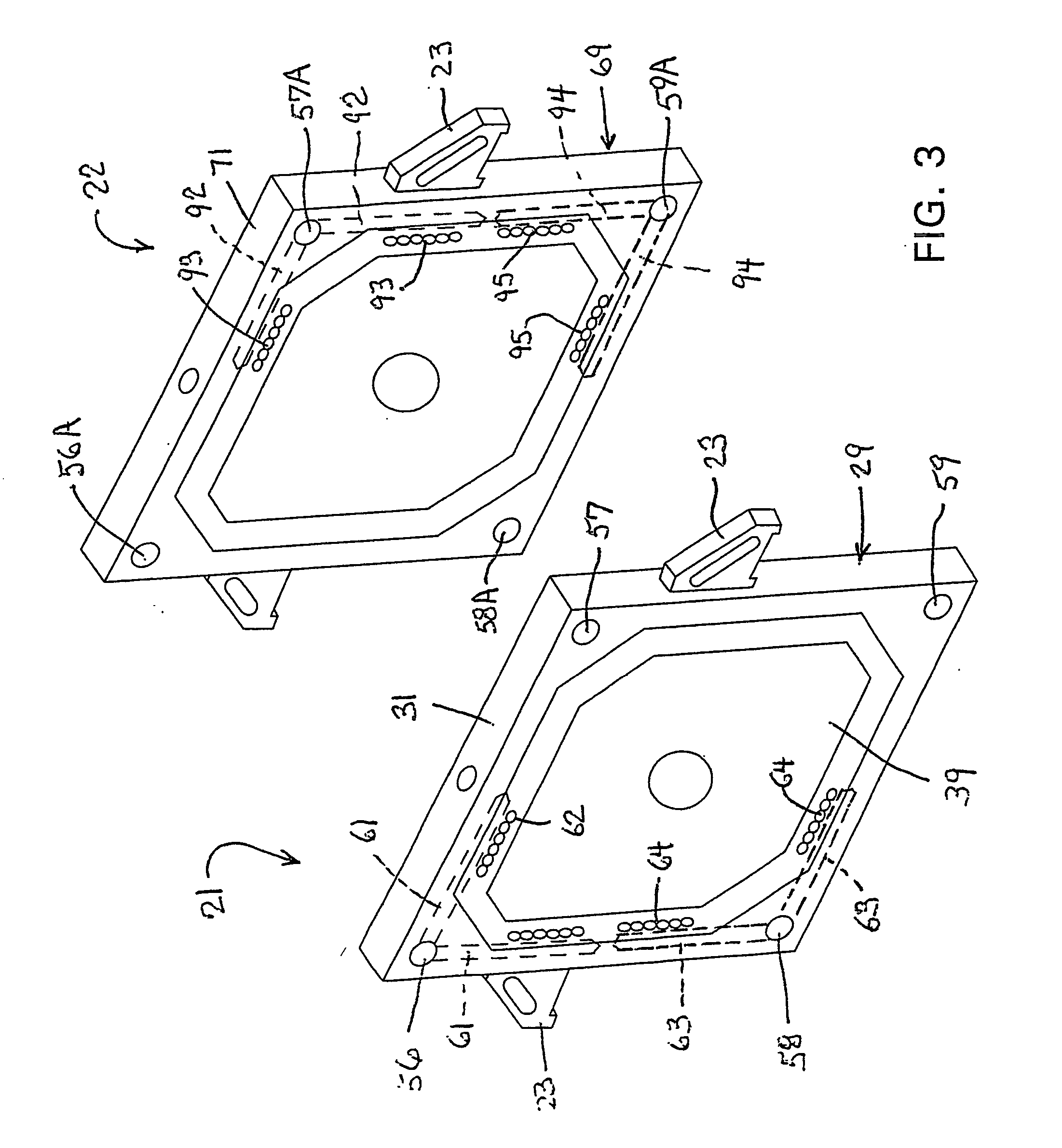
[0036] A plurality of filter plates, namely alternating membrane filter plates 21 and heat filt...


PUM

PropertyMeasurementUnit
flexibleaaaaaaaaaa
widthaaaaaaaaaa
heat transmittingaaaaaaaaaa

Abstract

A filter press (11) defined by a closable stack of filter plates defined by a first plurality of membrane filter plates (21) alternately disposed with a second plurality of heating-type filter plates (22). The membrane plates (21) have chamber-defining recesses on opposite sides thereof, with each recess (36) having a flexible membrane (39) associated therewith which can be pressurized from the rearward side so as to effect squeezing of the cake in the filtration chamber. Each heating plate (22) also has chamber-defining recesses (74) on opposite sides thereof, and the main center bottom wall (76) of each recess (74) has a metal heat transfer surface (77) associated therewith, the rear side of which is in intimate contact with a chamber or passage (79) which receives therein a high-temperature heat transfer fluid.

Description

FIELD OF THE INVENTION [0001] This invention relates to a filter press for dewatering slurry and, more specifically, to an improved filter press for permitting heating and drying of filter cake formed in filtration chambers of a filter press to permit more efficient separation of liquid from slurry, and the method for effecting such separation. BACKGROUND OF THE INVENTION [0002] Filter presses are well known and extensively utilized for separating solids from slurries. Such filter presses employ a plurality of filter plates which are held in contacting relationship between fixed and movable head members while the slurry is pumped into and through the press for collecting the solids in the form of cake between adjacent filter plates. When the press is full, the movable head is backed away from the plates into an open position and the plates are moved into an open position to permit discharge of the cake which is collected between adjacent pairs of plates. To permit movement of the pl...

Claims


Application Information

Patent Timeline
Patent Type & Authority Applications(United States)
IPC IPC(8): B01D25/164B01D25/21B01D35/18
CPCB01D25/21B01D25/215B01D25/284B01D35/18B01D25/285
Inventor HILDEBRANT, MARK W.MORLEY, TERRY A.BOSCH, MATTHEW J.MARCHEK, KENNETH A.
Owner UNITED STATES FILTER CORPORATION
Why Eureka
Try Eureka